4 minute read
DIS-ASSEMBLY AND RE-ASSEMBLY OF THE VALVE

Caution
Individual components of the oil pump are non serviceable. The pump may, however, be stripped for cleaning and examination purposes.
may be renewed if necessary.
Remove
Apply a airtightness product (P / N° 562228) to the sealing face as shown.
Caution
Before re-assembly remove all traces of old sealant from the joint faces.
Lubricate the ball seating with a light grease and push the two halves of the assembly together. Secure the rubber gaiter with two new plastic ties.
CAUTION !
All shafts and bearing should be lubricate with transmission fluid prior to assembly. To prevent possible contamination of hydraulic parts lint or cotton rags should not be used.
4WD VERSION : Position the front case as shown and using a suitably sized tube fit a new 4 wheel drive output shaft oil seal to a depth of 6mm below the housing face. Fill the seal lip with light grease.
Re-fit the oil pump assembly and sealing ring. Tighten 4 bolts to a torque of 13-23 Ib / ft. New copper washers must be fitted under the bolt heads.
If previously removed, replace the two plug and “O”ring assemblies and tighten to a torque of 30 to 4 Ibs /ft.
Replace
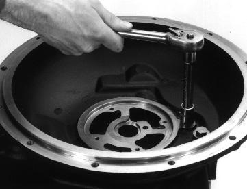
Slide the 1st / 2nd fork onto the 3rd / 4th rail then refit the 3rd / 4th shift fork and tighten the screw to a torque of 13 to 18 Ibs / ft. Hold the forks and rail in place on the output shaft then re-fit the complete assembly into the case. The shift rail should displace the dummy plug as it enters the bore.
CAUTION !
Check that the inner detent spring and ball have not become displaced and remove the loose dummy plug from the case sump.
Re-fit the 1st / shift rail and tighten the shift fork screw to a torque of 13 to 18 Ibs / ft. Check that the interlock ball is correctly positioned in between the two rails.
Replace the outer detent ball and spring. Tighten the plug to a torque of 30 to 40 Ibs /ft.
Lubricate
Position
Invert the case and replace the shim packs and bearing cups. The 2mm thick spacer shim should be fitted into the case first, then fit the remaining shims followed by the bearing cup. A light grease may be used to help hold the cups in the case.
Re-fit the rear case, (without sealant at this stage), and secure with at least 6 equally spaced bolts. When fitting the rear case be careful to avoid damaging the input shaft sealing rings.
Position a D.T.I. on the end of the input shaft as shown, and using a suitable pry bar through the side access hole, measure and note the shaft end float.
Attach a suitable shimming tool, (with a 12mm thread), to the end of the reverse idler shaft. Position a D.T.I. as shown, and using a pry bar lift the shaft, then measure and note the end float.
Attach a suitable shimming tool, (with a 12mm thread), to the end of the countershaft. Position a D.T.I. as shown, and using a pry bar lift the shaft, then measure and note the end float .
Replace the 4 «O»rings in the front case. (There are only 3 fitted on the 2 wheel drive model).
Attach a suitable shimming tool, (with a 12 mm thread), to the end of the output shaft. Position a D.T.I. as shown, and using a pry bar lift the shaft, then measure and note the end float..
Re-fit the rear case using an approved liquid gasket taking care not to damage the input shaft sealing rings. Tighten the 17 bolts to a torque of 33 to 47 Ibs / ft.
4WD VERSION : Attach a suitable shimming tool, (with a 12mm thread), to the end of the 4 wheel drive shaft. Position a D.T.I. as shown, and using a pry bar lift the shaft, then measure and note the end float.

Remove the rear case and add or remove shims as necessary to give .001” to .003” end float on all shafts. Repeat steps 11.17 to 11.22 until all shaft end floats are correct.
Replace the shaft end plug and O-ring assemblies. Note the special breather plugs fitted in the reverse idler position. Tighten to a torque of 30 to 40 Ibs / ft.
Lubricate the with fluid then re-fit the valve and tighten to a torque of 34 to 44
Lubricate
17 to 22 applications an additionnal sealing plug may be fitted.
Ensure the 4 «O»ring are in place then re-fit the control valve assembly and tighten the 4 caps crews to a torque of 5.0 to 6.3 Ibs / ft. The valve can only be fitted one way round as it is located by a small dowel pin.

Re-fit the strainer, spacer, «O»ring and cover plate. Then tighten the two screws to a torque of 13 to 23 Ibs / ft.
Apply a bead of RTV joint compound (P / N° 562228) to the gear case as shown.
Re-fit the drain plug and “O”ring assembly. Tighten to a torque of 25 to 40 Ibs / ft.
Re-fit the gear lever assembly and tighten the three bolts to a torque of 12 to 18 Ibs / ft.
Re-fit the filter housing and gasket. Tighten the two bolts to a torque of 33 to 47 Ibs / ft.
Re-fit the 4th gear lock out screw, (when this feature is not required a shorter blanking screw is fitted). On some
Lubricate the seals with a light grease and screw on a new oil filter.
4WD VERSION : Lubricate the seals with a light grease and re-fit the 4 wheel drive solenoid spool. Tighten to a torque of 15 to 20 Ibs / ft.

4WD VERSION : Re-fit the 4 wheel drive solenoid coil and nut. Tighten to a torque of 4 Ibs / ft maximum.
4WD VERSION : If previously removed re-fit the 4 wheel drive clutch supply pipe, apply air tightness product (P/N° 62175) to threads and thighten nuts to a torque of 5 to 7.5 Ibs / ft.