3 minute read
20.15 PRESSURE READING ON GEAR BOX

MACHINE TYPE and N° : ................................................... N° of HOURS : ..........................................
GEAR BOX TYPE and N° : ................................................
(To be carried out with gear box oil at 80° mini).
NEUTRAL FOWARD GEAR REVERSE GEAR
PUMP Mini r.p.m........................
Maxi r.p.m........................
CONVERTER Mini r.p.m........................
Maxi r.p.m........................
DRAINAGE Mini r.p.m........................
Maxi r.p.m........................
REVERSE GEAR Mini r.p.m........................
Maxi r.p.m........................
4 WD Mini r.p.m........................ Maxir.p.m........................
COMMENTS: ............................................................................................................................................................................................................................ .......................................................................................................................................................................................................................................................
* BREAKDOWN AT THE ORIGIN: ........................................................................................................................................................................................ ......................................................................................................................................................................................................................................................
* DETERMINED CAUSE OFTHE BREAKDOWN: ........................................................................................................................................................... ..................................................................................................................................................................................................................................................
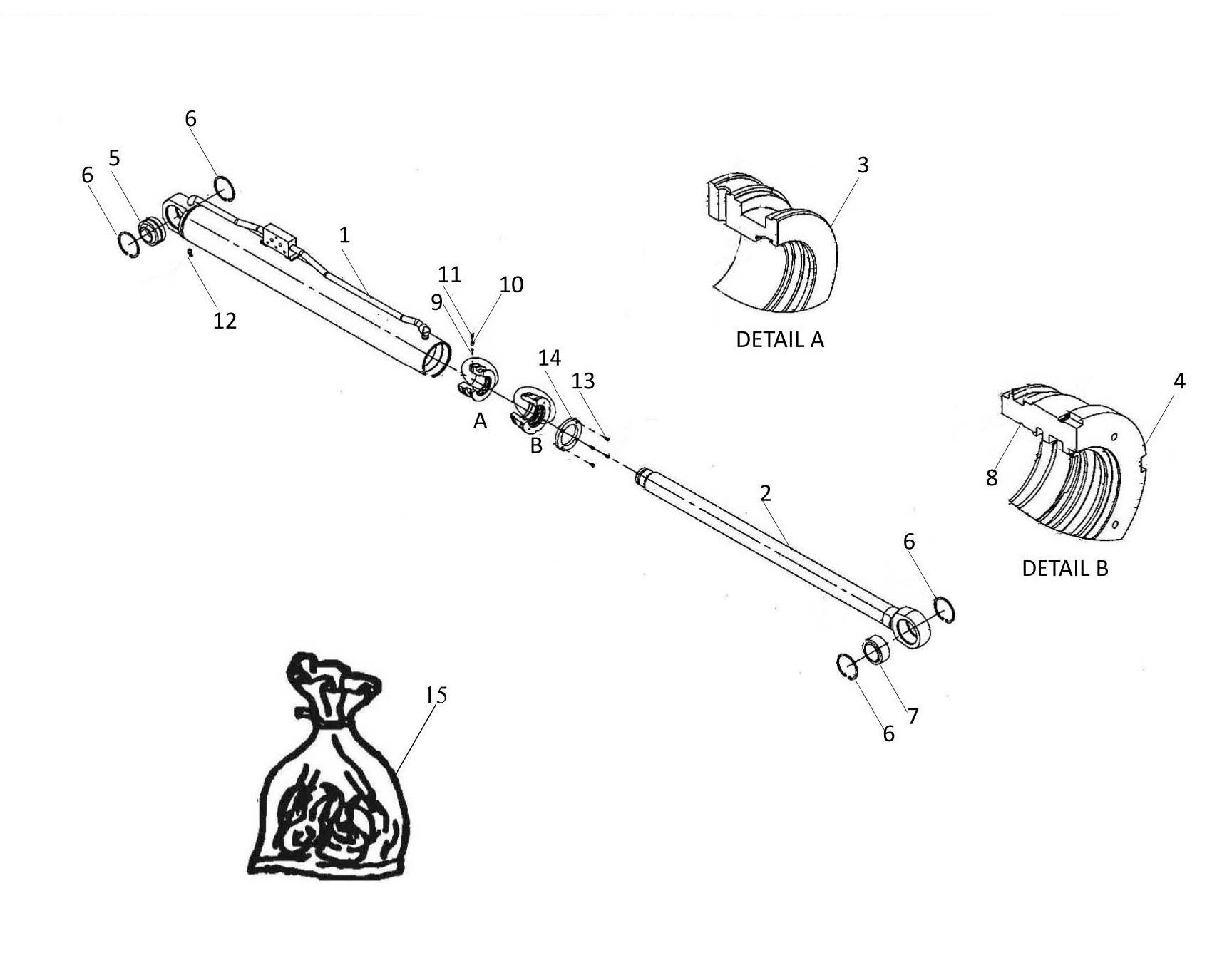
Number Designation
– 479307 Hand press.
– 479309 Input & Rev. Idler shaft brg. removal collet.
– 563390 4WD brg removal collet.
– 563391 Out put shaft front brg. removal collet.
– 563392 C / shaft and output shaft rear brg. removal collet.
– 563394 C / shaft front bearing remova lcollet.
– 563393 Input shaft spring compressor.
– 563395
Shimming Adapter
RECOMMENDED TUBE SIZES FOR REPLACING BEARINGS.
The dummy plug for re-fitting inner detent spring & ball can be made using a piece of bar 18mm dia. x 25 mm long.
20.17 SHAFT AND GEAR END FLOAT TOLERANCES
20.17.1 SHAFT END FLOATS
All shaft end floats should be 0.025 to 0.075 mm ( 0.001 to 0.003 ins. )
20.17.2 GEAR END FLOATS
Input shaft forward and reverse primary gears : 0.061 to 0.41 mm ( 0.0024 to 0.016 ins.).
Output shaft gears :
– 4th Gear : 0.20 to 0.56 mm. ( 0.008 to 0.022ins.)
– 3rd Gear : 0.38 to 0.84 mm. ( 0.015 to 0.033ins.)
– 2nd Gear: 0.36 to 0.56 mm. ( 0.014 to 0.022ins.)
– 1st Gear : 0.33 to 0.51 mm. ( 0.013 to 0.020ins.)
4 wheel drive : 0.051 mm. to 0.28 mm. ( 0.002 to 0.011 ins.).
BOLT TORQUES
DISASSEMBLY & RE-ASSEMBLY
20.18 GENERAL INFORMATION
We recommend that the procedures as outlined in this manual be followed when performing maintenance work on this transmission.
20.18.1 TOOLS
This transmission can be repaired with ordinary mechanics hand tools however this procedure is not only slow but may damage otherwise serviceable parts. To reduce maintenance costs and vehicle downtime, we recommend that the special tools listed in this manual be procured from a tool manufacturer, as stated.
20.18.2 CLEANLINESS
Transmission should be steam cleaned externally prior to disassembly. Seal all opening before cleaning to prevent entry of dirt and water which can damage serviceable parts. Dirt is abravise and will cause premature wear and failure of clutch plates, hydraulic valves and bearings.
*Due to the nature of operation of the hydraulic system cleanliness is of prime importance and the following guidelines should be observed:
Not lint or cotton rags should be used in order to prevent any possible clogging. – When fitting new clutch plates they should be soaked in clean new oil as recommended for 3hours. – All parts should be thoroughly cleaned and lubricated with new oil prior to reassembly.
20.18.3 BEARINGS
When a transmission is removed at relativity low mileage, bearings should be removed with pullers designed for the purpose. Wrap the bearings to keep outdirt.
Clean, inspect and lubricate all bearings just prior to reassembly. If accumulated mileage is over 1500 hours we suggest that all bearings be replaced.
Always use adapted tools to avoid damaging the new bearing assembly. Prefer the hot mounting of bearings, if possible. Use tools with plastic or brass tips.
20.18.4 REPLACEMENT PARTS
The exploded views of sub-assemblies which are incorporated in this manual are for the mechanic’s convenience and show the latest material. The parts are arranged in their correct order and may also be used as a reference for assembly or disassembly of this unit.
CAUTION
When inserting shim packs, it is essential that the thinnest shims are placed between the thicker shims to prevent any possible damage to the shims.
20.18.5 SEALS
The seals which have been removed on the disassembly shall be replaced by new on reassembly.
Invert the transmission on a suitable bench. For convenience the bench top should have a hole in it to accommodate the input shaft and pump. Remove 3 screws and withdraw the gear shift lever assembly.
Caution
The bearing cones and shims may fall from the rear case during removal.
Ensure both synchronisers are in the neutral position then remove the 1st / 2nd shift fork screw.
Remove the 3rd / 4th shift fork screw.
Caution
The bearing cones and shims may fall from the rear case during removal.
Withdraw the 1st / 2nd shift rod from the housing Then using a magnetic probe remove the interlock ball from the detent bore v.
Turn the 3rd / 4th shift rod through 90 degrees and withdraw from the housing.
Remove the detent plug, inner detent ball and spring.
Remove
Invert
Position the shaft in a soft jawed vice as shown.
Remove the thrust washer and needle bearing.
Remove and discard the 3 sealing rings.
Remove the reverse primary gear.
Using the appropiate bearing puller remove the rear bearing.
Remove the bearing, spacer, bearing and thrust washer.
Using
Re-new the piston sealing rings and “O”rings. To assist assembly bend the inner sealing ring into a heart shape as shown.
Replace an externally splined (plain) disc and then an internally splined (friction) disc alternately until six of each have been replaced.
Caution
New friction discs should be soaked in transmission fluid for a minimum of 3 hours prior to assembly.
Using transmission fluid to lubricate the seals push the piston into the drum.
Replace the clutch pack retaining plate and refit the retaining clip.
Replace the spring, retainer and circlip as shown.
Replace the thrust washer, bearing, spacer and bearing.
Using the appropriate tool compress the spring and locate the circlip ingo its groove.