7 minute read
Table 17: Maintenance Log


Date Hours
General Lubrication
Important: Use of lubricants not corresponding to manufacturer recommendations may invalidate warranty claims. Always dispose of waste lubrication oils and hydraulic fluids according to environmental laws or take to a recycling center for proper disposal. DO NOT pour fluids onto the ground or down a drain.
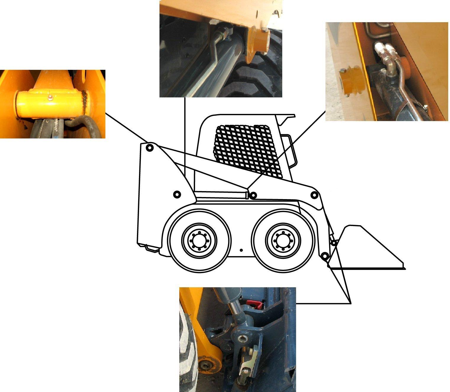
Maintenance Procedure
A. Front lift cylinder grease fittings (2).
B. Top lift arm grease fittings (2).
C. Back lift cylinder grease fittings (2).
D. Attachment hitch pivot points (2) – NOTE: Lubricate (D) from inside of pin.
E. Bottom tilt cylinder grease fittings (2).
See “Fluid Capacities/Lubricants” on page115 for proper grease specifications. Wipe dirt from the fittings before and after applying grease to prevent contamination. Replace any missing or damaged fittings. Avoid excessive greasing to minimize dirt build-up.
Removing Foreign Material
Remove dirt and other foreign matter from the following areas daily before operating the machine:
•Around the lift cylinders.
•At the front of the machine.
•On the attachment hitch, especially around the tilt cylinder.
•Around hydraulic oil reservoir breather.
•In the engine compartment.
•In the operator’s compartment.
Important: Build-up of foreign materials in these areas can interfere with machine operation, cause component damage or become a fire hazard.

Tilting the ROPS/FOPS
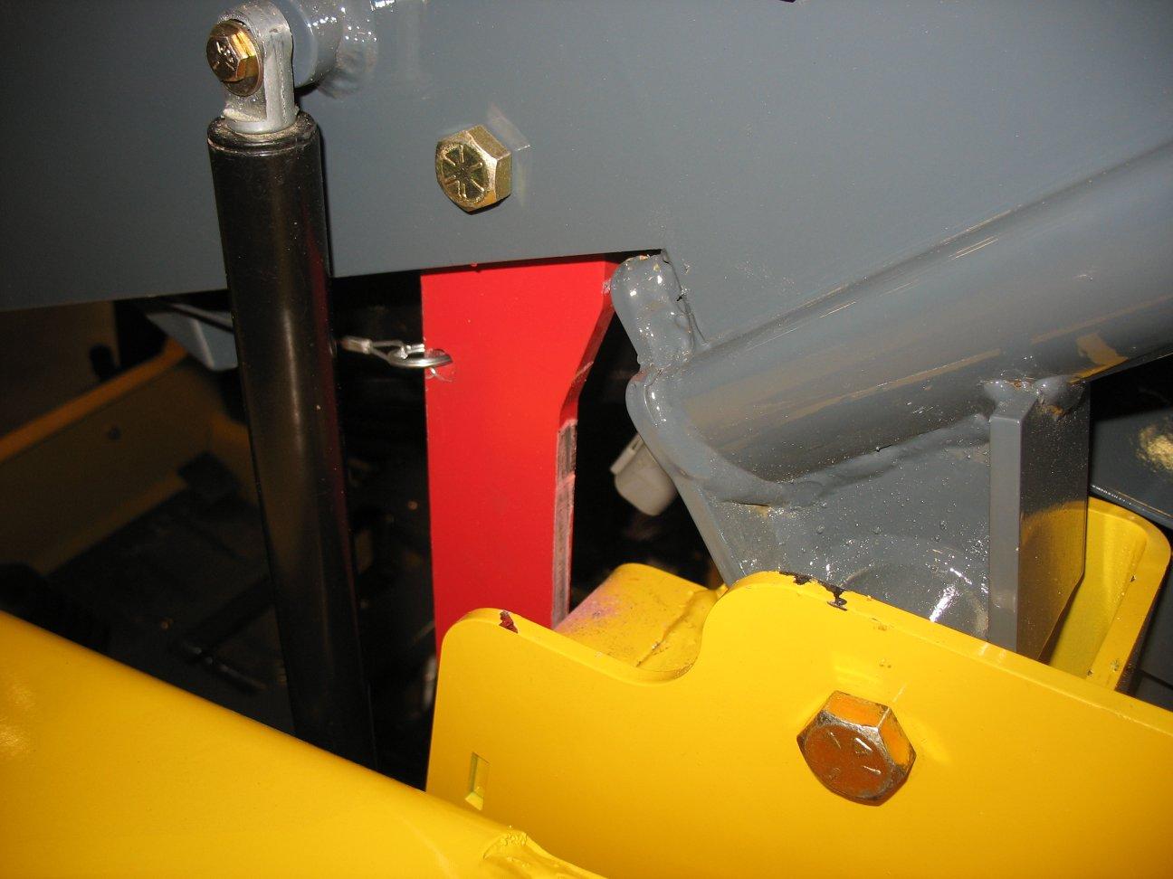
3.Tilt the ROPS/ FOPS up and back, moving the control handles out of the way. Tilt the ROPS/FOPS back slowly, until locking mechanism (B, Figure 87) locks the ROPS/FOPS in the raised position.
Note: A gas-charged spring helps balance the ROPS/FOPS as it tilts. A self-actuating lock mechanism engages to lock the ROPS/FOPS in the tilted position.
Lowering the ROPS/FOPS
Never operate the machine with the ROPS/FOPS in the raised position or removed. Be sure to reinstall the anchor bolts, washers and locknuts before using the machine. Torque to 43 Nm (32 lb-ft).
Always close the cab door before tilting the ROPS/ FOPS. Stay clear from underneath the ROPS/FOPS as it is tilted.
Be sure the lock is securely engaged when the ROPS/FOPS is raised. Properly support the ROPS/ FOPS when unlatching the lock mechanism and lowering the ROPS/FOPS.
Raising the ROPS/FOPS
1.Perform the “Mandatory Safety Shutdown Procedure” on page9.
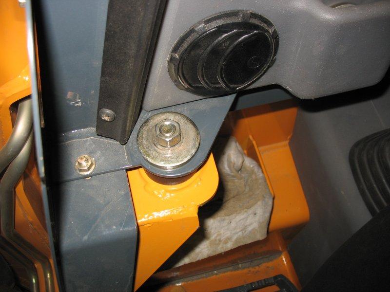
2.Remove hardware (A, Figure 86) at the front of the ROPS/FOPS.
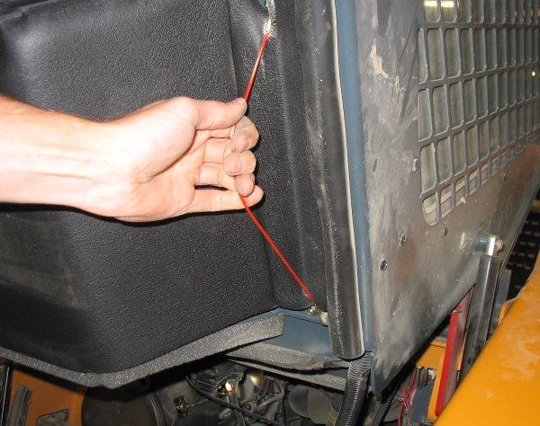
1.Lift the ROPS/ FOPS slightly while pulling lock mechanism release (C, Figure 88) toward the front.
2.Lower the ROPS/FOPS slowly onto the chassis, moving the control handles out of the way.
3.Secure the ROPS/FOPS in the lowered position with anchor hardware (A, Figure 86). Torque to 43 Nm (32 lb.-ft.).
Lifting the Machine
Use the following procedure to raise the machine so all four tires are off the ground for service:
Warning
Do not rely on a jack or hoist to hold the machine in the lifted position without additional blocking and supports. Serious personal injury could result from improperly lifting or blocking the machine.
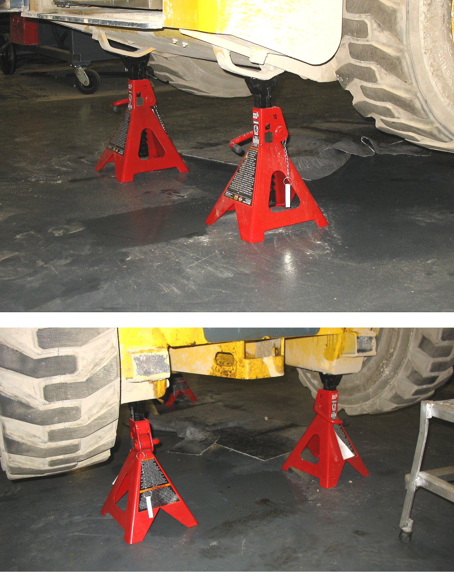
1.Use suitable blocks (solid wood, hard plastic or metal) or jackstands to properly block the machine so all four tires are raised off the ground.
2.Using a jack or hoist with a capacity greater than the fullyequipped weight of the machine (with all attached options), lift the rear of the machine until the rear tires are off the ground.
Important: Be sure the lifting apparatus is of sufficient capacity for the weight of the machine. Refer to “Weights” on page 93. If lifting the machine, refer to “Lifting the Machine Using a Crane or Hoist” on page74.
3.Stack blocks or place jackstands under the flat part of the chassis. Blocks should run parallel with, but not touch, the rear tires.
4.Slowly lower the machine until it rests on the blocks/ jackstands. If the tires still touch the ground, raise the machine, add more blocks or raise the jackstands and lower the machine onto the blocks.
5.Repeat this procedure for the front tires. When complete, all four tires will be off the ground so they can be removed.
Lowering the Machine
1.Using a jack or hoist, raise the front of the machine until it no longer rests on the front blocks or jackstands.
2.Carefully remove the blocking under the front of the machine.
3.Slowly lower the machine until the front tires are resting on the ground.
4.Repeat this procedure for the rear tires. When complete, all four tires will be on the ground with the blocks removed from under the machine.
Engine Maintenance
Engine Access
1.Lift the engine cover and pull the rear door latch (Z, Figure 90)up.
2.Carefully swing open the rear door. Note: Rear door prop (Y) near the top hinge pin of the door is used to secure the door open.
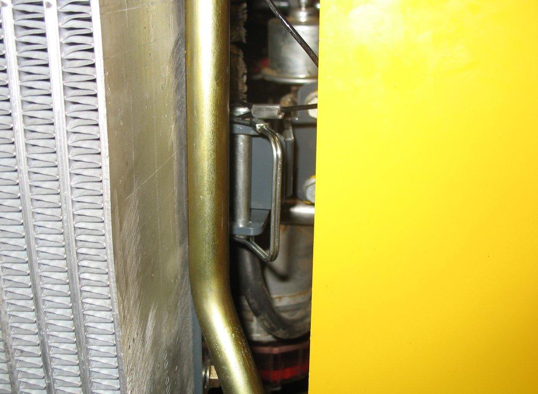
3.Additionally, the radiator swings out, providing greater access to the engine: a.Pull down on spring pin lock (C, Figure 91) to release pin (D). Lift pin (D) out of the bracket. b.Swing the radiator outward. c.When engine maintenance is complete, return the radiator back to the closed position and secure it in place with pin (D). Lock pin (D) in the bracket with spring pin lock (C).
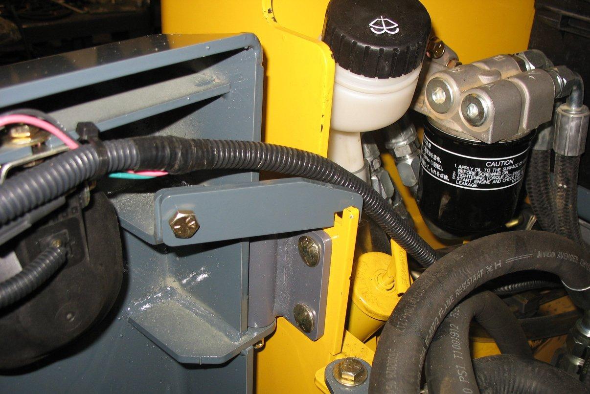
Engine Mounting Hardware Inspection
Changing Engine Oil and Filter
Refer to the “Maintenance Schedules” on page80 for the service interval for replacing the engine oil and filter.
1.Park the machine on a level surface.
Perform the Mandatory Safety Shutdown Procedure. Allow hot engine and hydraulic system components to cool before servicing.
All bolts that secure the engine mounting brackets to the engine and the chassis should be checked and re-tightened as necessary.
Checking Engine Oil Level
Check the engine oil level daily before starting the machine, or after every 10 hours of use.
1.Park the machine on a level surface.
2.Perform “Mandatory Safety Shutdown Procedure” on page9.
3.Wait until the engine has cooled.
4.Open the engine access cover and rear door.
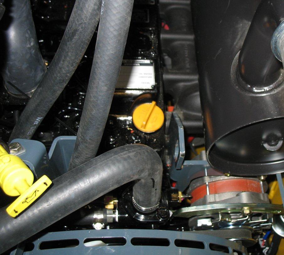
5.Twist engine oil dipstick (E, Figure 92) counterclockwise to unlatch it. Remove the dipstick from the engine.

6.Wipe the dipstick with a clean cloth and replace it in the engine. Push it in until it is fully inserted.
7.Remove the dipstick again. The oil level should be within the “Add” (G) and “Full” (H) markings.
8.If the oil level is below the “Add” marking: a.Clean the area around the oil fill cap (F) with a clean cloth. b.Remove fill cap (F). c.Add oil through the fill cap opening until the level reaches the “Full” mark. d.Replace and tighten fill cap (F).
Important: Do not over-fill the engine with oil; engine damage could result.
2.Perform “Mandatory Safety Shutdown Procedure” on page9.
3.Wait until the engine has cooled, but is not completely cold.
Note: Oil drains faster and more completely when warm.
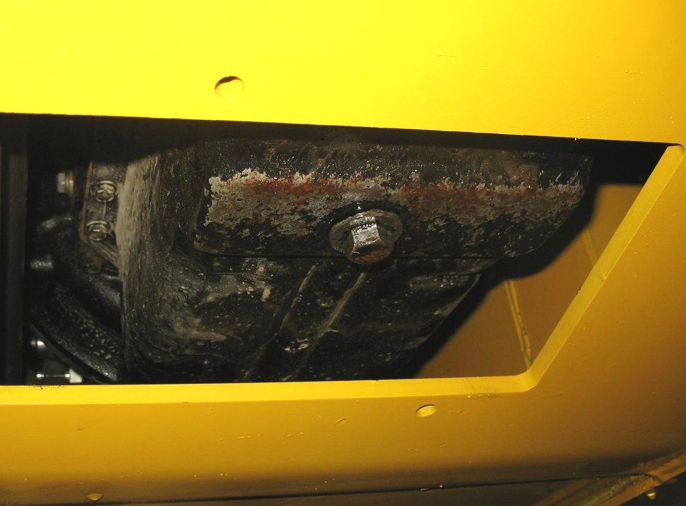
4.Remove the rear belly pan to access engine oil drain plug (X, Figure 93).
5.Position a waste oil collection container under the engine oil drain plug to catch draining oil.
Important: Dispose waste engine oil according to environmental laws, or take to a recycling center for proper disposal. DO NOT pour waste engine oil onto the ground or down a drain.
6.Remove drain plug (X) or (A) and allow engine oil to drain into the waste oil collection container.
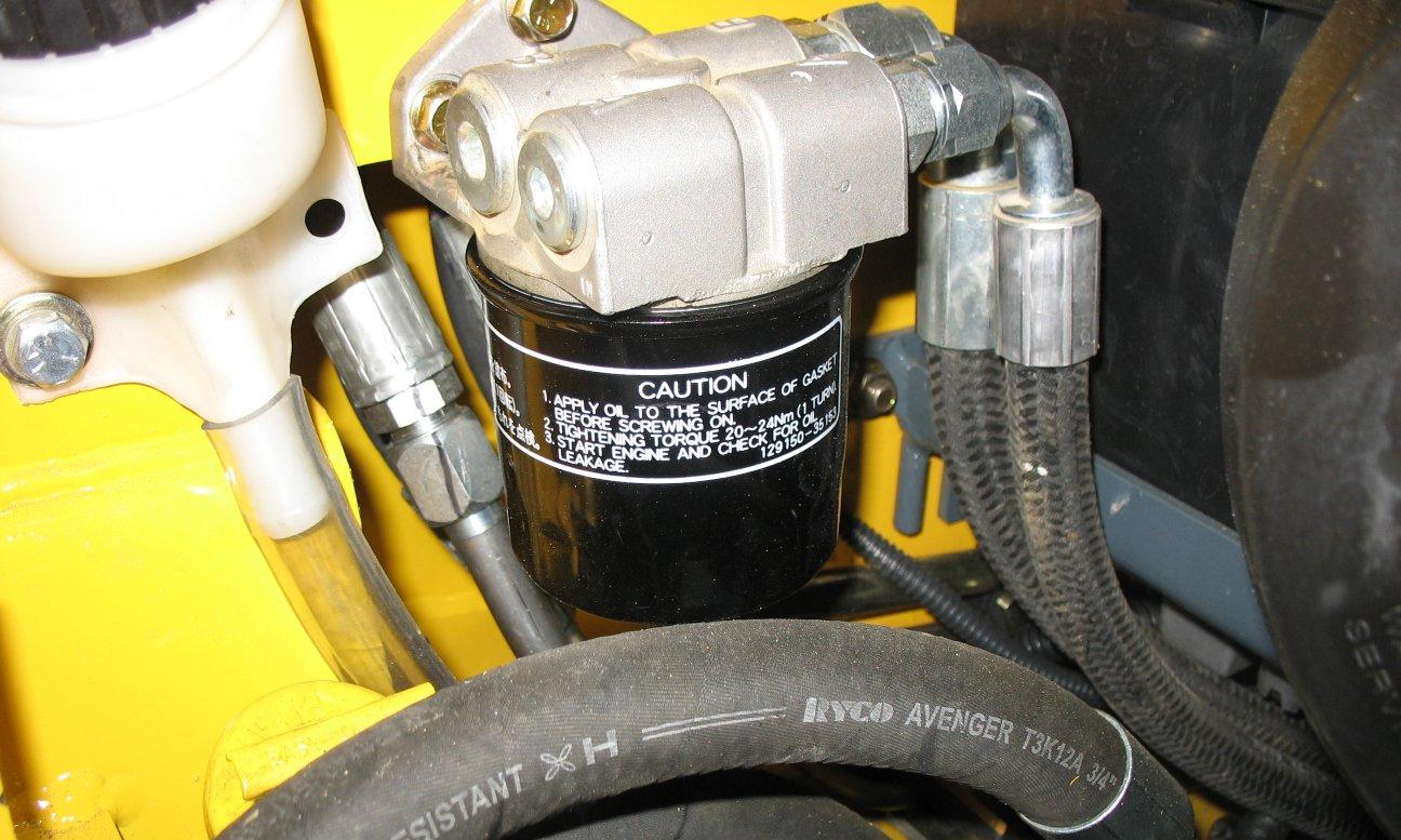
7.Remove oil filter (W, Figure 94), using a filter wrench if necessary. Carefully clean the filter head mounting surface with a clean cloth.
8.Put clean oil on the new oil filter gasket. Install the filter and tighten 3/4 of a turn past the point where the gasket contacts the filter head.
9.Reinstall and tighten the drain plug.
10.Clean the area around oil fill cap (E, Figure 92). Remove oil fill cap (E) and add the recommended type and amount of oil. See “Fluid Capacities/Lubricants” on page115. Replace and tighten oil fill cap (E) after the oil is added.
Note: Oil capacity listed is approximate. Always verify proper oil level with the engine oil dipstick.
Important: Do not over-fill the engine with oil; engine damage could result.
11.Start the engine and let it run for several minutes at low idle. Watch for leaks at the oil filter and drain plug. Stop the engine and wait for it to cool.
12.Check the oil level. Add oil if necessary until the oil level is at the “Full” mark (H, Figure 92) on the dipstick.
Fuel System Maintenance
Warning
Diesel fuel is flammable. Keep the machine away from open flames. Do not smoke when refueling or when working on the engine. Stop the engine before fueling.
Wear eye protection. The fuel system is under pressure and fuel could spray out when removing any fuel system component.
Wipe up spills immediately. NEVER use a shop rag to catch draining/leaking fuel. Vapors from the rag are flammable and explosive.
Failure to follow these instructions can cause fire and result in injury or death.
Caution
Use only proper types and grades of diesel fuel (See “Fluid Capacities/Lubricants” on page115).
Note: The fuel tank is filled at the factory with United States offroad grade diesel fuel, which is dyed red for identification. It may take several fillings of the fuel tank before the red dye is purged from the fuel system.
Adding Fuel
Warning
Keep open flames and sparks away from fuel. Static electricity can produce dangerous sparks at the fuel-filling nozzle. Do not wear polyester, or polyester-blend clothing while fueling. Before fueling, touch the metal surface of the machine away from the fuel fill to dissipate any built-up static electricity. Do not re-enter the machine but stay near the fuel filling point during refueling to minimize the build-up of static electricity. Do not use cell phones while fueling. Make sure the static line is connected from the machine to the fuel truck before fueling begins.
Ultra-Low Sulfur Diesel (ULSD) poses a greater static ignition hazard than earlier diesel formulations. Avoid death or serious injury from fire or explosion; consult with your fuel or fuel system supplier to ensure the entire fuel delivery system is in compliance with fueling standards for proper grounding and bonding practices.
1.Perform the “Mandatory Safety Shutdown Procedure” on page9.
2.Lift the engine cover.
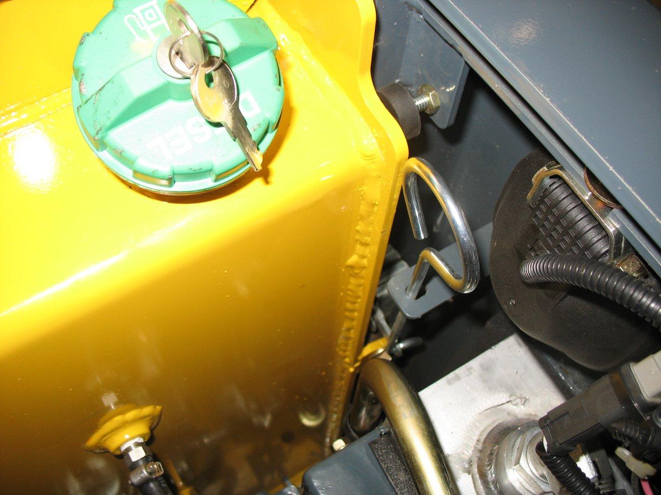
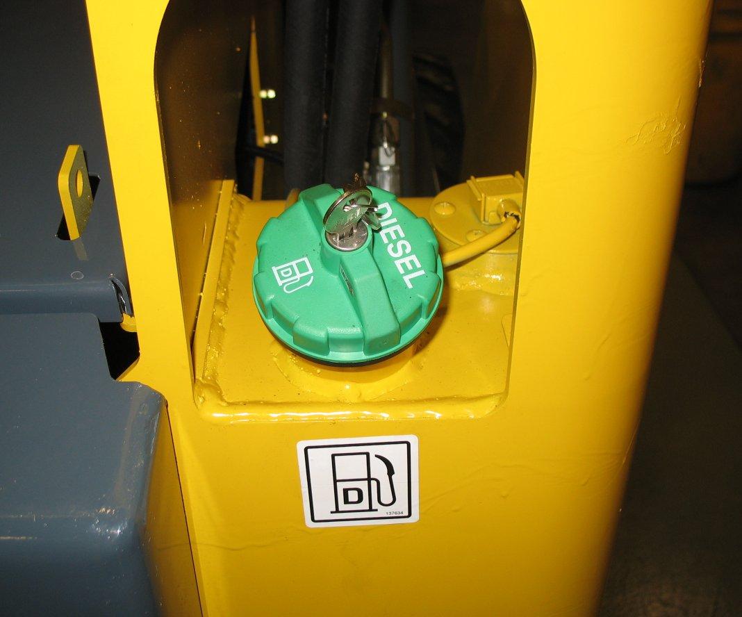
3.Using the ignition key to unlock fuel cap (F, Figure 95) and remove the fuel cap from the fuel filler neck.
Note: On Model R135, fuel cap (F)is located under the engine cover.
4.Fill the fuel tank by adding fuel through the fuel filler neck opening.
Important: See “Fluid Capacities/Lubricants” on page115 and the engine operation manual for proper fuels. Use of improper fuels can cause engine damage.
5.When the fuel tank is full, replace and lock fuel cap (F) in the fuel filler neck opening.
Important: To provide for proper fuel system venting, do not top off the fuel tank.