11 minute read
Starting the Engine


Warning
Be familiar with the “Mandatory Safety Shutdown Procedure” on page9 before starting the machine. Always perform this procedure before exiting the machine.
Note: The machine cannot be push- or tow-started. Attempting to push/tow start the machine may damage the drive systems of both the machine and the push/tow vehicle.
Warning
Do not use starting fluid (ether). An explosion can result, which can cause engine damage, injury or death.
1.If the machine is equipped with the battery disconnect switch, check that switch is the “ON” position. See “Battery Disconnect Switch” on page52.
2.Carefully step up onto the back of the bucket or attachment and grasp the hand-holds. enter the operator’s compartment and sit in the operator’s seat. Adjust the seat as required. See “Operator’s Seat” on page29.
Caution
All controls must be within easy reach. The operator must be able to move all controls through the complete range of motion.
3.Close the door, if so equipped. Perform the seat switch safety interlock test on page30.
4.Fasten the seat belt(s). See “Fastening/Unfastening the Seat Belt” on page30.
Warning
Always fasten the seat belt before operating the machine. Repair or replace any damaged seat belt and lock parts before operation.
5.Lower the operator restraint bar.
Important: The operator restraint bar must be lowered before the engine can be started.
6.Place the lift/tilt, drive and auxiliary hydraulic controls into the neutral position.
7.Make sure no persons are hazardously close to the machine.
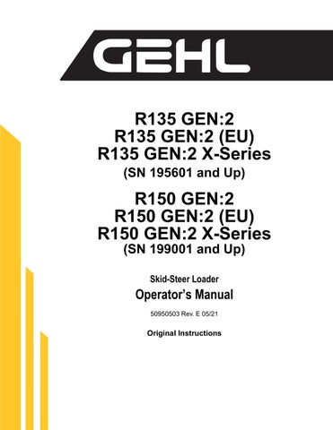
8.Turn the ignition key one detent clockwise to the ON/RUN position. If the engine is cold, the pre-heat () indicator activates. For information about starting in colder ambient temperatures, see “Cold-Starting” on page58.
9.When the pre-heat () indicator goes out, turn the ignition key all the way clockwise to the START position to engage the starter.
Important: The recommended limit of continuous starter engagement is 15 seconds, and the starter must never be energized for more than 30 seconds. If the starter is energized for 20-30 seconds, the ignition should be turned off for one minute or longer. To protect the starter (DPF Models), the E-ECU system turns off the starter circuit if it is energized for 30 seconds or longer. The starter will remain de-energized for 30 seconds more before the engine can be restarted.
Important: If the engine fails to start within 15 seconds, turn the key all the way counter-clockwise to the OFF position and check for engine error codes on the information center display (page108). Allow the starter to cool for 20 seconds and repeat steps 8 and 9.
Cold-Starting
If operating in temperatures below 32°F (0°C), the following are recommended:
•Replace the engine oil with the proper viscosity oil according to the engine operator’s manual.
•Make sure the battery is fully charged.
•Install an optional block heater on the engine. A block heater is recommended for starting in temperatures below 20°F (-7°C). Contact your dealer for engine heater options.
Run the engine at 1800 rpm with no load for 5 minutes to warm the engine and hydraulic fluid to operating temperature before operating the machine.
Note: Depending upon coolant temperature, 50° F (10° C) or below, the low idle engine speed is automatically increased during a five minute warm-up period or until the coolant reaches a specified temperature.
Important: In ambient temperatures below -10° C (14° F), an engine block heater is recommended and is required below temperatures below -15° C (5° F) to reduce starter load and aid engine warm up. Starting the machine at these temperatures without a block heater will result in multiple glow/crank cycles or possible extended cranking time approaching 20 seconds.
After Starting
1.Check that the charge () and oil pressure () indicators go out after the engine starts.
Important: If the charge () and/or the engine oil pressure () indicators do not go out when the engine is running, shut down the engine immediately and correct the problem. Damage to the engine may result if engine is run and the problem is not corrected.
2.Press the parking brake button on the control keypad to release the parking brake.
Note: The parking brake () indicator on the control keypad is lit when the parking brake is engaged.
3.Perform restraint bar safety interlock system test on page30.
4.Check for proper steering operation.
5.Check for excessively smoky exhaust (“Engine Troubleshooting” on page101):
•Black smoke indicates poor and/or incomplete diesel fuel combustion.
•Blue smoke indicates engine oil combustion.
•White smoke indicates incomplete diesel combustion and/or coolant in the combustion chamber. Watch for persons hazardously close to the machine after starting and during machine operation.
Important: Do not run the engine at full throttle until it reaches operating temperature, or damage to the engine can result. Perform the following warm up procedure after starting before using the machine.
Important: Do not run the engine at high speed (above 20% of full throttle) for extended periods when the machine is not under load. Damage to the engine can result.
Warm Up
Do not operate the machine until the hydraulic system reaches operating temperature. When cold, hydraulic response is slow and can be unpredictable, presenting an unsafe condition. Damage to the machine can also result.
1.After starting, allow the engine to run at low idle with no load for a minimum of 5 minutes without operating the drive, lift, tilt or auxiliary functions.
2.Run the engine at 1800 rpm with no load for 5 minutes.
3.Raise the lift arm so the attachment is off the ground.
4.Extend and retract each of the cylinders several times with no load.
5.Travel slowly forward and backward several times.
6.In cold weather, tilt the attachment all the way forward and keep it there for 20-25 seconds. Repeat this step until the attachment tilt speed is normal.
Run-In Period
The performance and service life of the machine is heavily dependent on using the machine carefully during its first 100 operating hours.
•Do not operate the machine at the maximum rated operating capacity.
•Do not run the engine at a high speed for extended periods of time.
•Increase the load gradually while varying the engine speed.
•Follow the maintenance schedule. See “Maintenance Schedules” on page80.
Stopping the Machine
When stopping the machine, perform the “Mandatory Safety Shutdown Procedure” on page9. Raise the operator restraint bar, unfasten the seat belt(s) and grasp the hand-holds while climbing out of the operator’s compartment.
Important: Do not stop the engine at full throttle. Damage to the engine can result.
Note: The machine is equipped with a spring-applied automatic parking brake. The parking brake is applied when the operator restraint bar is lifted, the operator’s leaves the operator’s seat, the engine is shut off, or the parking brake switch is actuated.
Engine Stalling
If the engine should stall for any reason during operation, always turn the ignition keyswitch all the way counter-clockwise to the OFF position and place the lift/tilt, drive and auxiliary hydraulic controls into the neutral positions before restarting the engine according to “Starting the Engine” on page58.
Parking the Machine
Park the machine away from traffic on firm, level ground. If this is not possible, park the machine across the incline and block the tires to prevent movement.
After performing the “Mandatory Safety Shutdown Procedure” on page9, perform the following:
•Check for coolant, fuel and/or oil leaks. Inspect all hoses, working components, covers and chassis for damage or advanced wear. Check for loose or missing parts. Repair or replace damaged, leaking, worn or otherwise compromised components before starting the machine again.
•Fill the fuel tank. See “Fluid Capacities/Lubricants” on page115 for proper fuel specifications.
•Remove any dirt and/or debris from the engine compartment.
•Remove any mud/dirt from the chassis. Clean any dirt or water from the cylinder rod surfaces to prevent corrosion and protect the cylinder seals.
•If parking the machine for an extended period, lock the cab door (if so equipped) and the engine compartment. Take the keys with you.
Brake Release Operation (Option)
The machine may have, as an option, a brake release system installed. The brake release system releases the parking brake, allowing the machine to be towed for short distances.
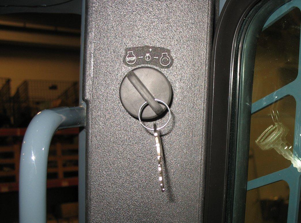
1.Locate the brake release jack (Z, Figure 55) and handle. Depending on your particular model, it may be necessary to remove covers and/or open the rear door of the machine.
2.Position the brake release receiver (Y) and insert the jack handle.
3.Push down and hold the plunger (Z) against the brake release.
4.Jack the brake release to build pressure. As pressure builds, plunger (X) stays down and no longer needs to be held.
5.Continue to jack the brake release until jacking resistance no longer increases.
Note: The brake release has a pressure relief which prevents damage to the travel motors.
6.Tow the machine for short distances only, such as towing it onto a trailer. Depending on the internal leakage rate of the travel motors, the machine may roll easily with the brake release activated, or the tires may skid until the oil is forced from the motors.
7.Reset the parking brake by pulling up on plunger (X) or starting the machine.
Jump-starting
If the battery is discharged or does not have enough power to start the engine, jump-start the engine as follows:
Two people are required for safe jump-starting. An additional person is required to remove the jumper cables with the operator remaining in the operator's seat once the engine is running. Start the engine from the operator’s seat with all controls in “neutral.”
Before utilizing the brake release, be sure to secure the machine with wheel chocks or tow lines. Verify the travel path of the machine is clear of personnel before operating the brake release system.
NEVER make jumper cable connections directly to the starter solenoid of either engine.
To reduce the risk of a short circuit, keep metal parts on your clothing and metal jewelry away from the battery.
Do not jump-start a frozen battery, or it may explode. A discharged battery can freeze at 14°F (-10°C).
Wear safety glasses and avoid leaning over the batteries while jump-starting.
To avoid personal injury, closely follow the procedure, step-by-step.
Important: The external power source must deliver 12 volts, DC.Supply voltages higher than 12V can damage the electrical systems of both machines. Only use jumper cables that are in good condition.
Important: The booster battery must have a voltage of 12-volts.
1.Turn the ignition keyswitches of both machines to the OFF position. Be sure the controls in both machines are in the neutral position and the machines are NOT touching each other. If the machine with the booster battery has a drive transmission, place the transmission into neutral and apply the parking brake.
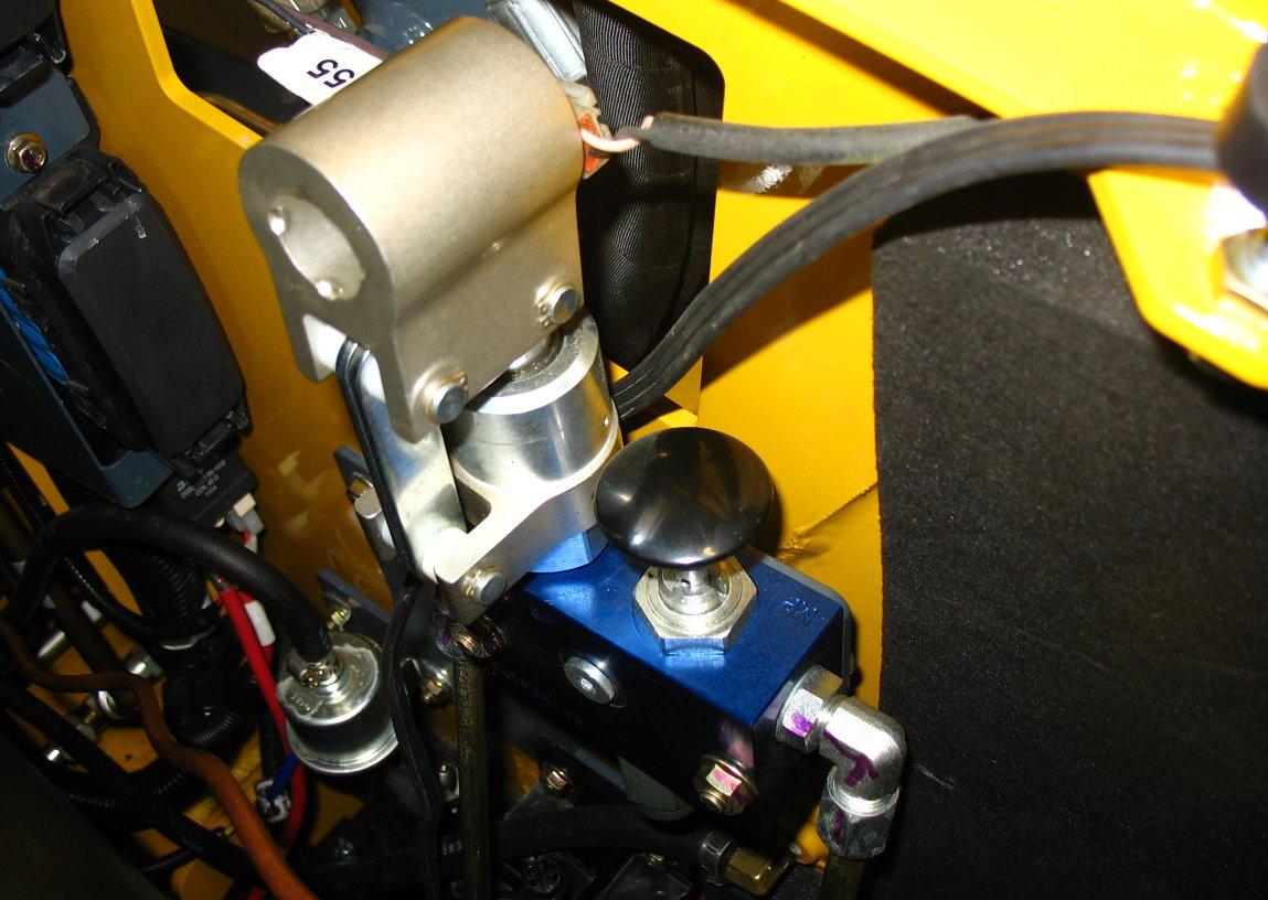
2.Open the engine compartment to provide access to the discharged battery (Figure 56). If the machine is equipped with a battery disconnect switch (see “Battery Disconnect Switch” on page52), be sure the switch is in the ON position.
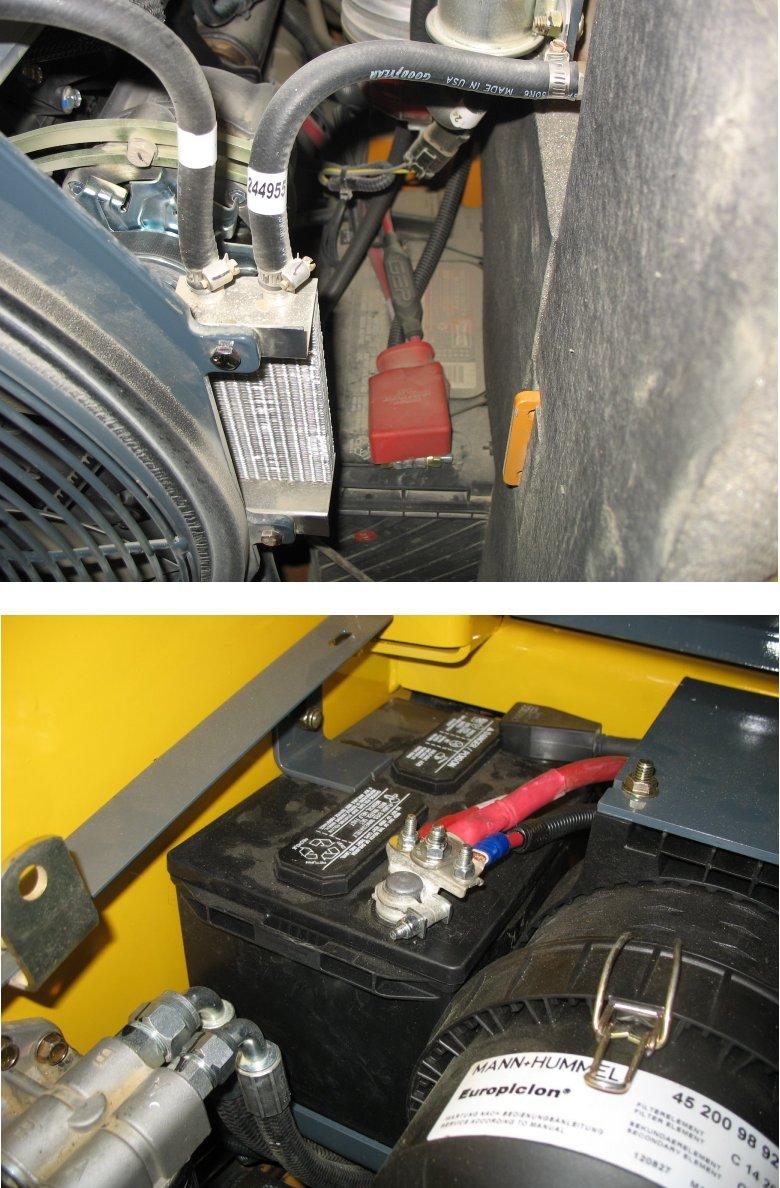
3.Route the jumper cables so that they cannot catch on any moving objects or components and connect the positive jumper cable to the positive (+) terminal (A, Figure 57) on the discharged battery.
Important: Prevent the other positive jumper cable clamp from touching any metal other than the positive (+) remote battery terminal.
4.Connect the other end of the positive jumper cable to the positive (+) terminal (B) on the booster battery.
5.Connect the negative jumper cable to the negative (-) terminal (C) on the booster battery.
6.Connect the other end of the negative (-) jumper cable to an unpainted frame surface (D)inside the engine compartment of the machine with the discharge battery. Connect the cable as far as possible away from the battery.
Important: Prevent the other negative jumper cable clamp from touching any metal other than the frame of the machine with the discharged battery.
Do not connect the other end of the negative jumper cable clamp to the negative terminal (-) on the discharged battery. Gas emerging from the battery may ignite if sparks are formed.
7.Start the machine with the discharged battery. See “Starting the Engine” on page58. If the engine does not start immediately, stop cranking after 10 seconds and repeat starting procedure after approximately 30 seconds.
Note: Alternately, a third person can start the machine with the booster battery, to avoid excessive drain on the booster battery.
8.Once the machine with the discharged battery is running, disconnect the jumper cables in reverse order of connection. Be careful not to short the jumper cables together when disconnecting.
9.Run the machine for at least 30 minutes to re-charge the battery.
Travel Drive Operation
Refer to travel drive control information starting on page62.
Transport on Public Roads
Refer to “Loading and Transporting the Machine on a Transport Vehicle” on page73 if it is necessary to transport the machine a long distance. For short distance travel on public roads, attach an SMV (Slow-Moving Vehicle) emblem (purchased locally) to the back of the machine. For highway operation, install the optional flashing beacon.
Never allow anyone to enter the machine travel path and/or inside the turning radius of the machine. Signal your intention to move by sounding the horn.
Traveling should be performed with the attachment in transport position. See “Attachment Transport Position” on page 63.
Avoid sudden stops, starts or turns. Do not raise the restraint bar while traveling. Raising the restraint bar will apply the parking brake abruptly. Loss of control could result.
Do not turn the ignition keyswitch to the OFF position while traveling. Sudden braking will occur and loss of control could result.
Always check and look behind you before and while traveling in reverse. Traveling in reverse without checking and looking could result in collision with a person or obstacle.
Remove obstacles in the machine’s path before traveling with a load.
Driving on an Incline
When traveling on an incline, travel with the heavy end pointing uphill.
Driving over Rough Terrain
When traveling over rough terrain, activate the Hydraglide™ ride control system and drive slowly with the bucket lowered in the transport position (“Attachment Transport Position” on page 63). See“Hydraglide™ Ride Control System (Option)” on page 63 for details about activating Hydraglide™.
Important: Follow the applicable legal regulations of the country and locality where the machine is used. Only the attachments listed in the operation license or vehicle papers are admissible for driving on public roads.
Transport Hydraulics Lock-out (Option)
When driving the machine on public roads activate the transport hydraulics lock-out on machines equipped with this option. Postion the lift arm in the transport postion and press the hydraulics lockout button (A) to deactivate the attachment lift and tilt hydraulics and prevent inadvertent lift arm movement. Pressing the button again will toggle hydraulic function back on.
Note: Attachment tilt and lift hydraulics are deactivated when LED (B) is lit.
Lift Arm Operation
Refer to lift and tilt control information starting on page62. Do not lift loads exceeding rated operating capacity. See “Payloads/Capacities” on page116.
The float mode can be used where the engine has stopped, is unable to be started, and lowering the lift arm is necessary to allow the operator to exit the machine. See “Lift Arm Float” on page49.
Attachment Transport Position
Hydraglide™ Ride Control System (Option)
Hydraglide™ cushions lift arm loads during transport. It provides a smoother ride over uneven surfaces.
Always carry loads in transport position to minimize the possibility of tipping or rollover accidents and unstable balance conditions that can cause loss of control.
Carry materials 200-300 mm (8-12”) above the ground (A, Figure 59), and adjust as necessary to clear obstacles. Generally, carry the load as low as safely possible. Tilt buckets back, as shown in Figure 59, to prevent spilling material.
Warning
When ride control is activated, the lift arm may drop slightly without a load, or several inches with a heavy load.
Warning
Do not use Hydraglide™ when using pallet forks.
Important: Do not use Hydraglide™ when digging. Precise control of the digging operation is difficult with the Hydraglide™ option activated.
Note: Hydraglide™ is not effective if the lift arm is lowered against the chassis frame.
See “Hydraglide™ Ride Control System (Option)” on page50 for details about Hydraglide™ control.
Lift Arm Float
Make sure the bucket is lowered to the ground before activating the lift arm float. Activating float with an attachment raised will cause the lift arm to fall to the ground, which can cause severe injury or death.
Do not drive forward with the lift arm float activated. Damage to the machine and/or loss of control can result.
Float allows the lowered lift arm to follow the ground contour while traveling over changing ground conditions. It is useful when grading surfaces while driving the machine in reverse.
Note: Lift arm float is not effective if the lift arm is lowered against the chassis frame.
See “Lift Arm Float” on page49 for details about the lift arm float control.