15 minute read
Table 8: T-Bar Controls


Ref. Control Description
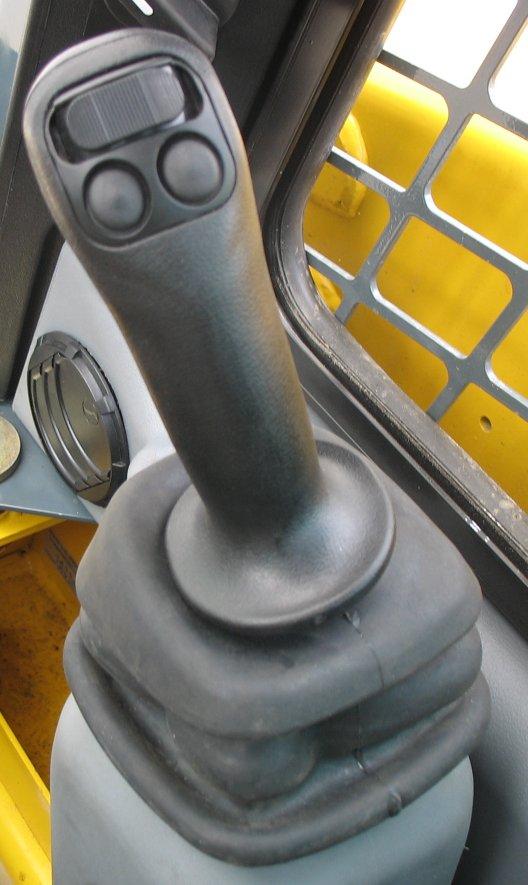
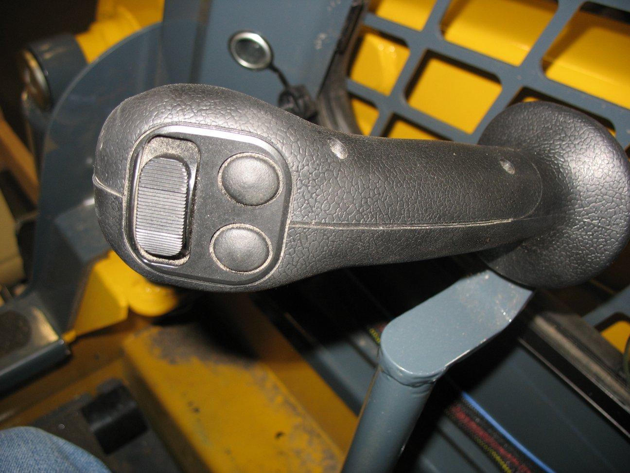
GAuxiliary Hydraulics Rocker Switch
Controls auxiliary hydraulics flow direction and amount. See “Auxiliary Hydraulic System” on page54.
H Auxiliary Hydraulics Continuous Flow Latch Trigger Works with Auxiliary Hydraulics Rocker Switch to latch/unlatch auxiliary hydraulics continuous flow. See “Auxiliary Hydraulic System” on page54.
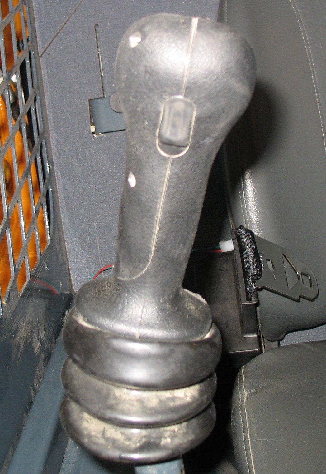
On machines equipped with T-bar controls, the left T-bar controls the drive, and the right T-bar controls the lift/tilt.
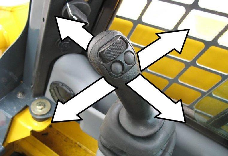
Drive
Control (Left T-Bar)
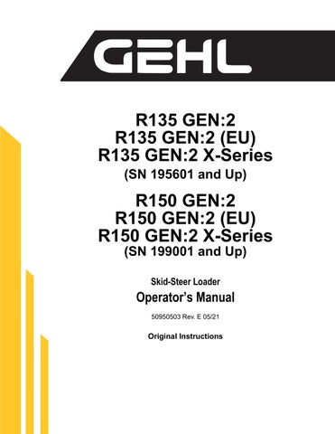
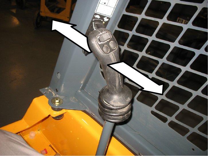
Forward, reverse, travel speed and turning maneuvers are controlled using the left T-bar (Figure 26):
A.To go forward, push the left T-bar forward.
B.To go in reverse, pull the left T-bar rearward.
C.To turn right, twist the control clockwise.
D.To turn left, twist the control counter-clockwise. For gradual turns, twist the T-bar slightly; for sharp turns, twist the T-bar further.
Turns while moving forward or in reverse can be made by twisting the T-bar while also pushing it forward or pulling it back.
Moving the T-bar farther from neutral increases the speed steadily to the maximum travel speed.
Note: Tractive effort decreases as speed increases. To get maximum tractive effort, move the T-bar only slightly away from the neutral position.
Note: The engine will stall if the control is moved too far forward when loading the bucket.
Warning

Make sure the controls are in neutral before starting the engine. Operate the controls gradually and smoothly. Excessive speed and quick control movements without regard for conditions and circumstances are hazardous and could cause an accident.
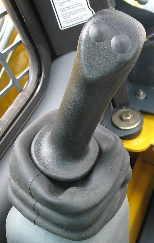
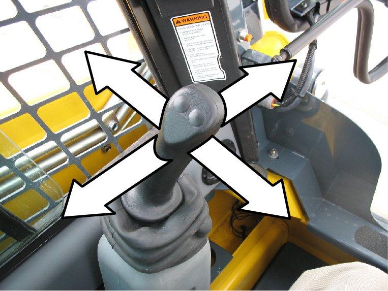
Lift/Tilt Control (Right T-Bar)
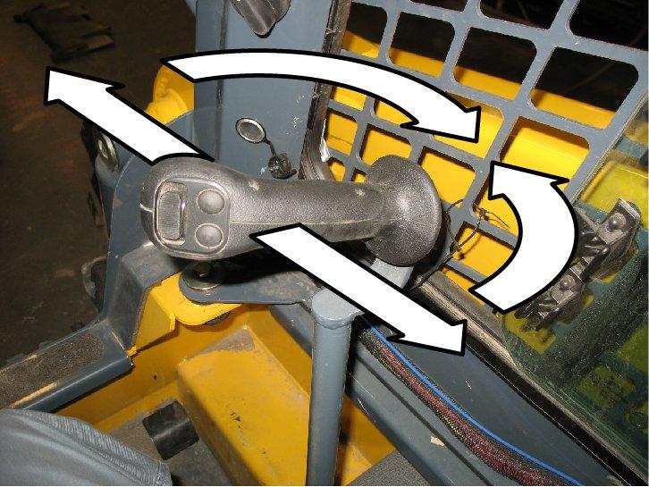
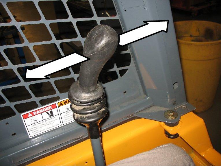
Lift arm raise and lower, and attachment tilt are controlled using the right T-bar (Figure 27):
A.To lower the lift arm, push the right T-bar straight forward.
B.To raise the lift arm, pull the right T-bar straight rearward.
C.To tilt the attachment forward and down, twist the right T-bar clockwise.
D.To tilt the attachment up and back, twist the right T-bar counter-clockwise.
The lift arm can be tilted while raising or lowering by twisting the T-bar while also pushing it forward or pulling it back.
Note: The speed of the lift/tilt motion is proportional to the amount of T-bar movement and engine speed.
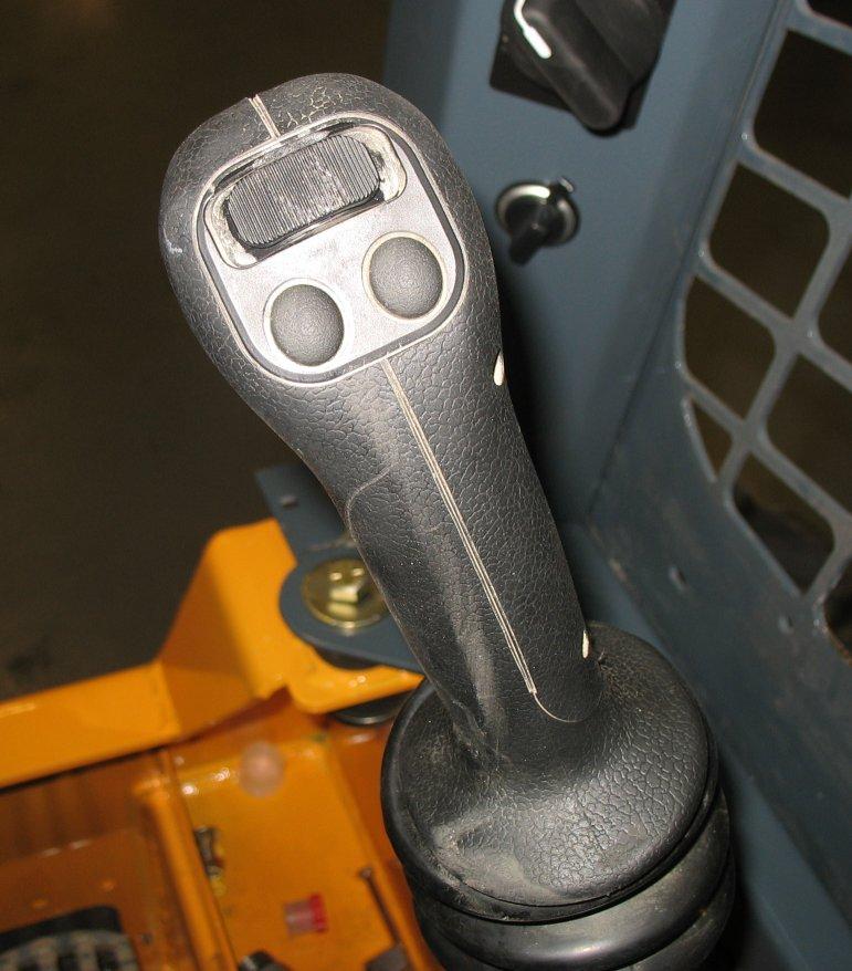
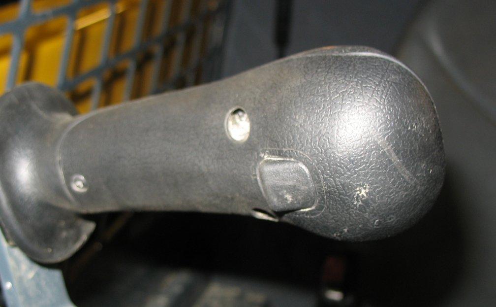
Joystick Controls
On joystick-equipped machines, the left joystick controls the travel drive, and the right joystick controls the attachment lift and tilt.
Left Joystick Right Joystick
Table 9: Joystick Controls
Ref. Control Description
ALeft Joystick
Controls drive forward, reverse, turn, and speed. See “Drive Control (Left Joystick)” on page46.
BRight Joystick Controls lift arm raise/lower, float, and attachment tilt. See “Lift/Tilt Control (Right Joystick)” on page46.
CTwo-Speed Selection Button Not Available.
DHorn Button Activates horn.
EHydraglide™ Button Activates Hydraglide™. See “Hydraglide™ Ride Control System (Option)” on page50.
F Float Button Activates Float. See “Lift Arm Float” on page49.
GAuxiliary Hydraulics Rocker Switch Controls auxiliary hydraulics flow direction and amount. See “Auxiliary Hydraulic System” on page54.
H Auxiliary Hydraulics Continuous Flow Latch Trigger Works with Auxiliary Hydraulics Rocker Switch to latch/unlatch auxiliary hydraulics continuous flow. See “Auxiliary Hydraulic System” on page54.
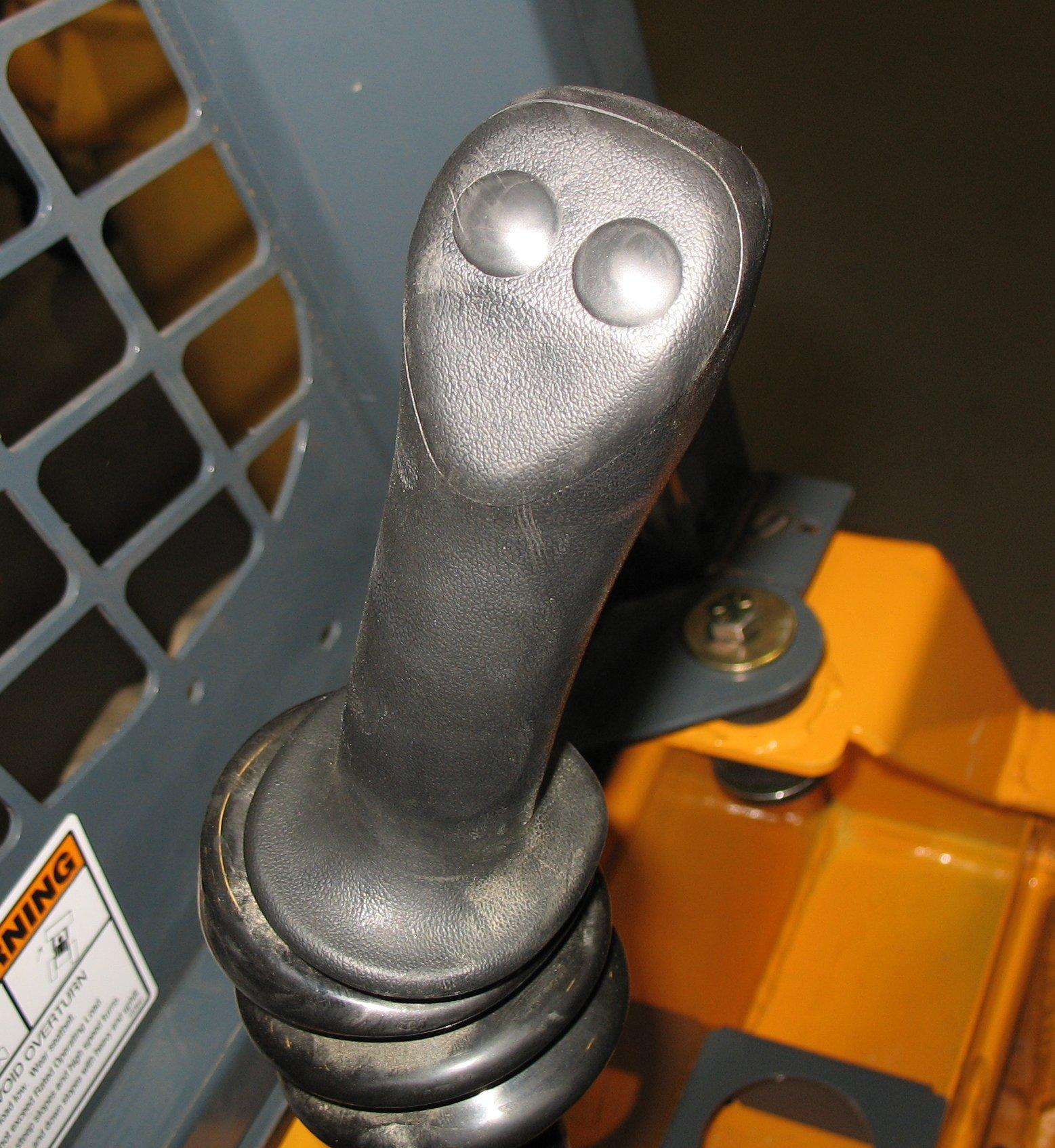
Drive Control (Left Joystick)
Forward, reverse, travel speed and turning maneuvers are controlled using the left joystick (Figure 29):
A.To go forward, push the left joystick forward.
B.To go in reverse, pull the left joystick rearward.
C.To turn right, push the left joystick to the right.
D.To turn left, push the left joystick to the left.
E.To go forward and to the right, push the left joystick forward and to the right.
F.To go rearward and to the right, pull the left joystick rearward and to the right.
G.To go forward and to the left, push the left joystick forward and to the left.
H.To go rearward and to the left, pull the left joystick rearward and to the left.
Warning
Make sure the joystick controls are in neutral before starting the engine. Operate the controls gradually and smoothly. Excessive speed and quick control movements without regard for conditions and circumstances are hazardous and could result in loss of control and cause an accident.
Moving the joystick farther from neutral increases the speed steadily to the maximum travel speed. Tractive effort decreases as speed increases. For maximum tractive effort, move the joystick only slightly away from the neutral position. The engine may stall if the control is moved too far forward when loading the bucket.
Lift/Tilt Control (Right Joystick)
Lift arm raise and lower, and attachment tilt are controlled using the right joystick (Figure 30):
A.To lower the lift arm, push the right joystick straight forward.
B.To raise the lift arm, pull the right joystick straight back.
C.To tilt the attachment forward and down, move the right joystick to the right.
D.To tilt the attachment up and back, move the right joystick to the left.
E.To lower the lift arm while tilting the attachment forward and down, move the right joystick forward and to the right.
F.To lower the lift arm while tilting the attachment up and back, move the right joystick forward and to the left.
G.To raise the lift arm while tilting the attachment forward and down move the right joystick rearward and to the right.
H.To raise the lift arm while tilting the attachment up and back, move the right joystick rearward and to the left.
Note: The speed of the lift/tilt motion is directly proportional to the amount of joystick movement and engine speed.
Hand and Foot Controls
On hand and foot controlled-equipped machines, the hand controls are used to control the travel drive, and the foot controls are used to control the attachment lift and tilt.
Left Hand Control
Right Hand Control
Foot Controls
Table 10: Hand and Foot Controls
Ref. Control Description
ALeft Hand Control Controls travel drive forward, reverse, turn, and speed. See “Drive Control (Hand Controls)” on page48.
BRight Hand Control Controls travel drive forward, reverse, turn, and speed. See “Drive Control (Hand Controls)” on page48.
CTwo-Speed Selection Button Not Available.
DHorn Button Activates horn.
EHydraglide™ Button Activates Hydraglide™. See “Hydraglide™ Ride Control System (Option)” on page50.
F INACTIVE Button is inactive on Hand and Foot Controls.
GAuxiliary Hydraulics Rocker Switch Controls auxiliary hydraulics flow direction and amount. See “Auxiliary Hydraulic System” on page54.
H Auxiliary Hydraulics Continuous Flow Latch Trigger Works with Auxiliary Hydraulics Rocker Switch to latch/unlatch auxiliary hydraulics continuous flow. See “Auxiliary Hydraulic System” on page54.
I Left Foot Control Control lift arm raise and lower. See “Lift/Tilt Control (Foot Controls)” on page48.
J Right Foot Control Controls attachment tilt. See “Lift/Tilt Control (Foot Controls)” on page48.
Drive Control (Hand Controls)
Forward, reverse, travel speed and turning maneuvers are controlled using the hand controls (Figure 32):
A.To go forward, push both hand controls forward.
B.To go in reverse, pull both hand controls rearward.
C.To turn right, push the left hand control farther forward than the right.
D.To turn left, push the right hand control farther forward than the left.
E.To spin turn clockwise, push the left hand control forward and pull the right hand control rearward.
F.To spin turn counter-clockwise, push the right hand control forward and pull the left hand control rearward.
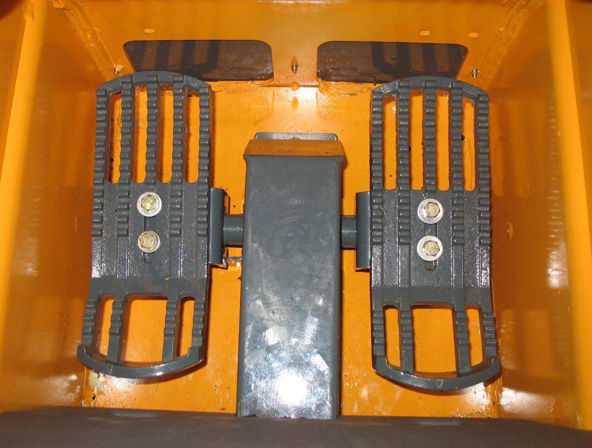
Lift/Tilt Control (Foot Controls)
Lift arm raise and lower, and attachment tilt are controlled using the foot controls (Figure 33):
Make sure the controls are in neutral before starting the engine. Operate the controls gradually and smoothly. Excessive speed and quick control movements without regard for conditions and circumstances are hazardous and could cause an accident.
Moving the hand controls farther from neutral increases the speed steadily to the maximum travel speed. Tractive effort decreases as wheel speed increases. For maximum tractive effort, move the hand controls only slightly away from the neutral positions. The engine will stall if the hand controls are moved too far forward when loading the bucket.
A.To lower the lift arm, push the front of the left foot pedal down.
B.To raise the lift arm, push the back of the left foot pedal down.
C.To tilt the attachment forward and down, push the front of the right foot pedal down.

D.To tilt the attachment up and back, push the back of the right foot pedal down.
Note: The speed of the lift/tilt motion is directly proportional to the amount of pedal movement and engine speed.
Lift Arm Float
On Joystick Controls
1.Lower the attachment to the ground.
2.Press button (A, Figure 34) to activate float:
•Press button (A) momentarily to apply float momentarily.
Make sure the attachment is lowered to the ground before activating the lift arm float. Activating float with the lift arm raised will cause the lift arm and attachment to fall to the ground, which can cause severe injury or death.
Warning Warning
The float mode can be used where the engine has stopped, is unable to be started, and lowering the lift arm is necessary to allow the operator to exit the machine.
Float allows the lowered lift arm to follow the ground contour while traveling over changing ground conditions..
To activate lift arm float:
On T-Bar Controls
1.Lower the attachment to the ground.
2.Push Right T-Bar (B)all the way forward (Figure 27)into the detent (“float”) position. This position allows the lowered lift arm to “float” while traveling over changing ground conditions.
3.To remove lift arm from the detent (“float”) position, pull the Right T-Bar (B) out of the detent position. This returns the lift arm to normal operation.
•Press and hold button (A) for 5 seconds to activate continuous float. Press button (A) again to deactivate continuous float. The float indicator () on the control pad is lit when float is activated on Joystick Control types.
On Hand and Foot Controls
1.Lower the attachment to the ground
2.To place the lift arm in the detent (“float”) position, use your toes to push the left pedal all the way down (A) into the detent. This position allows the lowered lift arm to “float” while traveling over changing ground conditions.
3.To remove lift arm from the detent (“float”) position, use your heel to push the left pedal down (B) out of the detent position. This returns the lift arm to normal operation.
Hydraglide™ Ride Control System (Option)
transport. Deactivate Hydraglide™ when working with heavy loads, such as when picking up excavated material.
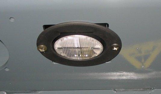
Beacon/Position/Work Lights
Warning Warning
When Hydraglide™ ride control is activated, the lift arm may drop slightly without a load, or several inches with a heavy load.
The optional beacon, the rear red position lights. and the front and rear work lights are all operated using button (Z).
Do not use Hydraglide™ when using pallet forks.
Hydraglide™ cushions lift arm loads during transport. It provides a smoother ride over uneven surfaces.
Press button (E, Figure 35) to activate Hydraglide™ ride control. Press button (E)again to deactivate.
When Hydraglide™ is activated, the Hydraglide™ indicator () on the control pad is lit.
Note: Hydraglide™ is automatically deactivated when the machine is shut off.
Important: Do not use Hydraglide™ when digging. Precise control of the digging operation is difficult when Hydraglide™ is activated.
Activate Hydraglide™ when driving on public roads, for lighter loads, and for light off-road
Note: The rear work lights and red position lights are located at the top of the rear door. The front work lights are located at the top front corners of the ROPS/FOPS. The beacon/position/work lights control button is located on the control keypad.
• Beacon and Position Lights: Press button (Z) once to activate the beacon and the rear red position lights. LED (Y) is lit when the beacon and the red position lights are on.
• Beacon, Position and Front Work Lights: Press button (Z) twice to activate the beacon, the rear red position lights and the front work lights. LED (U) is lit when the beacon, the position lights, and the front work lights are on.
Note: If the optional road lights are installed, this turns on both front and rear work lights. Also, if the roads lights are on, they toggle off when the work lights turn on
• Beacon, Position, and Front and Rear Work Lights: Press button (Z) three times to activate the beacon, the rear red position lights, and the front and rear work lights. Both LEDs (Y and U) is lit when the beacon, the red position lights, and the front and rear work lights are on.
Note: If the optional road lights are installed, this turns off all lights.
• Off: Press button (Z) a fourth time to turn off the beacon, the red position lights and the work lights. Both LEDs (Y and U) are off when the beacon and all lights are off.
HVAC (Option)
Machines with optional heat/ cool have two control buttons on the accessory keypad on the left door pillar for controlling the heater fan and heater temperature.
A. Cab Heat/Cool: Controls cab heat/cool. Press button as desired to set cab heat/cool; subsequent pressings increase heat from low to high. LEDs above the button are lit according to the low, medium and high heat settings.
NOTE: Cab heat/cool requires fan to be activated by pressing button (B).
B. Fan Speed: Controls cab air circulation fan. Press button (B) once for low setting, twice for medium, and three times for high. LEDs above the button are lit according to the low, medium and high fan settings. Press button (A) a forth time to deactivate air circulation fan.
Windshield Wiper/Washer Machines may be equipped with a wiper and washer on the rear window, machines equipped with a cab door are equipped with an additional wiper and washer on the front windshield.
A. Windshi eld Wiper: Controls the front windshield wiper on machines equipped with a cab door. Press button (A) once for continuous setting, twice for 3 second delay, and three times for 6 second delay. LEDs above the button are lit according to the selected setting. Press button (A) a forth time to deactivate the front windshield wiper.
B. Rear Window Wiper (EU only): Controls the back window wiper. Press button (B) once for continuous setting, twice for 3 second delay, and three times for 6 second delay. LEDs above the button are lit according to the selected setting. Press button (B) a fourth time to deactivate the rear window wiper.
C. Windshield Washer: Push and hold button (C) to activate the windshield washer spray and wiper. Release the button to stop the spray; wiper continues for 5 seconds.
D. Rear Window Washer (EU only): Push and hold button (C) to activate the rear window washer spray and wiper. Release the button to stop the spray; wiper continues for 5 seconds.
Dome Light
The dome light is located on the right side of the ROPS/ FOPS headliner.
When the ignition is off, if the dome light is centered, the light is activated by either sitting in the operator’s seat or by pressing certain buttons on the control keypad.
Note: The light will deactivate after approximately 10 seconds, if the ignition is turned on, or if the light is rotated by pressing to either side (T, Figure 39).
When the ignition is on, the light is activated by rotating it to either side (T, Figure 39); the light is deactivated by rotating it to the center.
If the light is centered, the light will activate when the ignition is turned off.
Note: The light will deactivate after approximately 10 seconds, if the ignition is turned on, or if the light is rotated by pressing on either side (T, Figure 39) of the light.
Accessory Plug
The 12V accessory plug (C, Figure 40) is located at the bottom of the right door pillar.
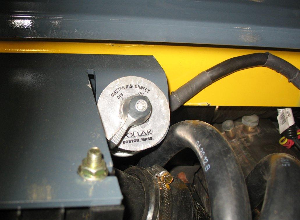
Battery Disconnect Switch
The optional battery disconnect switch (D, Figure 41) is located inside the engine compartment. Turn the switch to the OFF position to disconnect the battery from the electrical system.
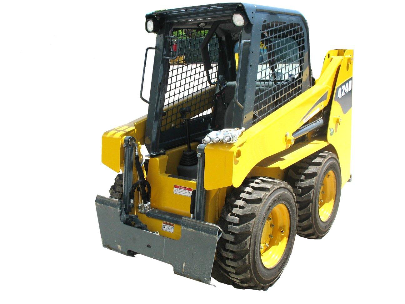
Attachment Mounting
The machine is equipped with either the standard manual AllTach® hitch or optional Power-A-Tach® system hitch for mounting a bucket or other attachments.
All-Tach® Hitch
A manual latch lever (E, Figure 42) engages the latch pins, which lock the attachment onto the hitch. While standing outside the machine, rotate the lever all the way to the right (as viewed while facing back at the machine from the front) to engage the locking pins to lock the attachment onto the hitch. Rotate the lever all the way to the left to disengage the locking pins. Refer to “Connecting Attachments” on page64 for more information.
Locking pins (F)must be fully extended through the holes in the attachment frame before using the attachment. The attachment could fall off if it is not locked on the hitch and cause serious injury or death.
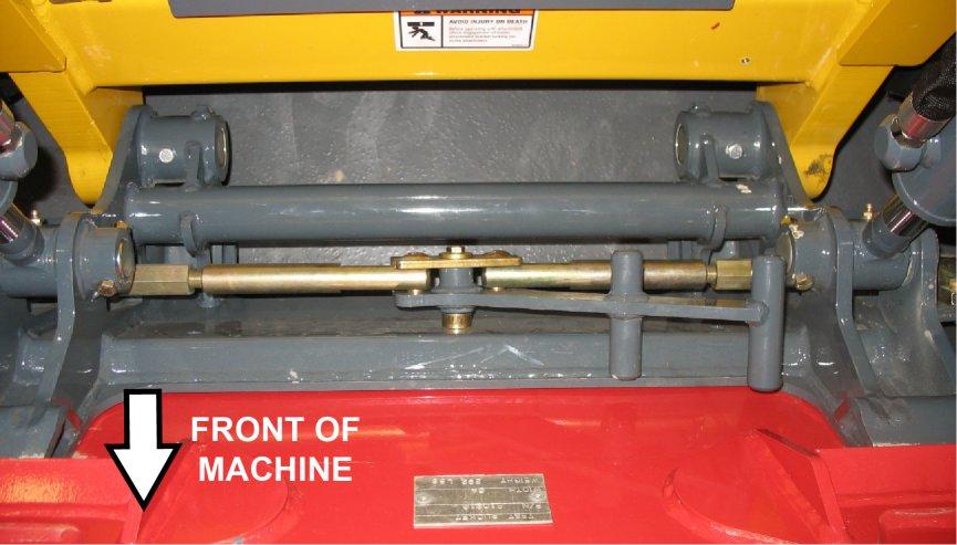
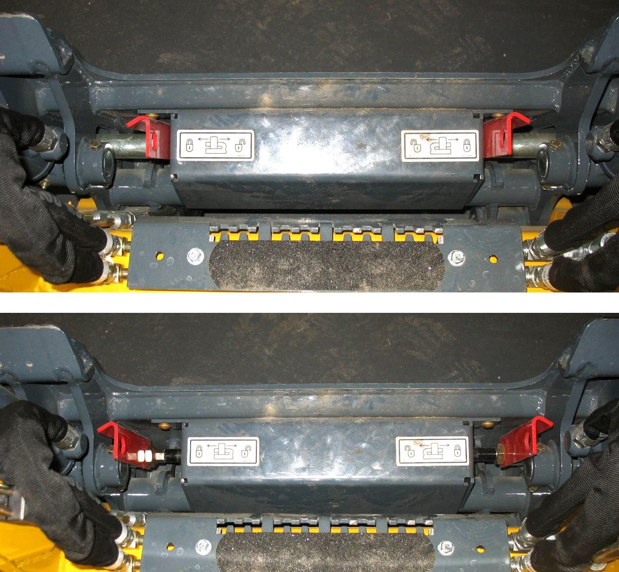
Power-A-Tach® System
Buttons (G and H, Figure 44) on the control keypad are used to operate the Power-A-Tach® System hitch. Refer to “Connecting Attachments” on page64 for more information.
Note: The Power-A-Tach® system hitch will not operate if the restraint bar is raised.
To retract the hitch pins to the unlocked position: With the machine running, and the parking brake disengaged, press and hold the Power-A-Tach® unlock button (H, Figure 44)on the control keypad until flags (P, Figure 45) move as far as they can to the center of the hitch.
To extend the hitch pins to the locked position: With the machine running, and the parking brake disengaged, press and hold the Power-A-Tach® lock button (G, Figure 44) on the control keypad until flags (Q, Figure 45) move as far as they can to the outside of the hitch.
To prevent unexpected release of the attachment from the hitch, make sure the locking lever is rotated all the way to the right (as viewed while facing back at the machine from the front) and the locking pins (F, Figure 43) extend down through the attachment frame.
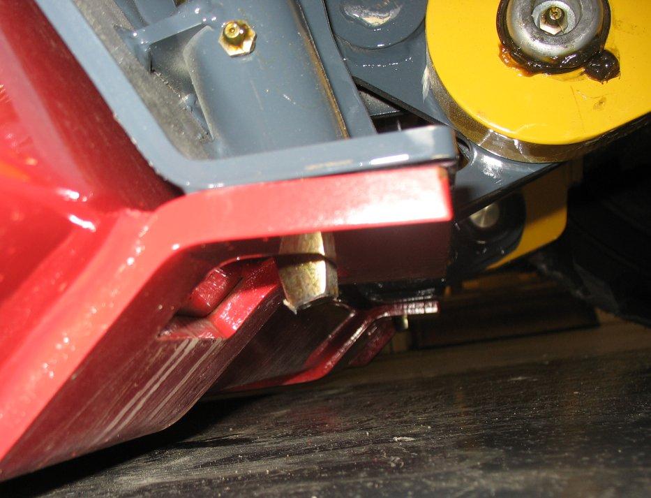
To prevent unexpected release of the attachment from the hitch, make sure the latch pins are secure by verifying that the pin flags (Q, Figure 45) have moved fully to the outside of the hitch and the locking pins (F, Figure 46) extend down through the attachment frame.
Locking pins (F)must be fully extended through the holes in the attachment frame before using the attachment. The attachment could fall off if it is not locked on the hitch and cause serious injury or death.
Auxiliary Hydraulic System
Auxiliary hydraulics are used with attachments requiring hydraulic power.
Warning
Always make sure the auxiliary hydraulic control is in neutral before starting the engine or disconnecting the auxiliary hydraulic couplers.
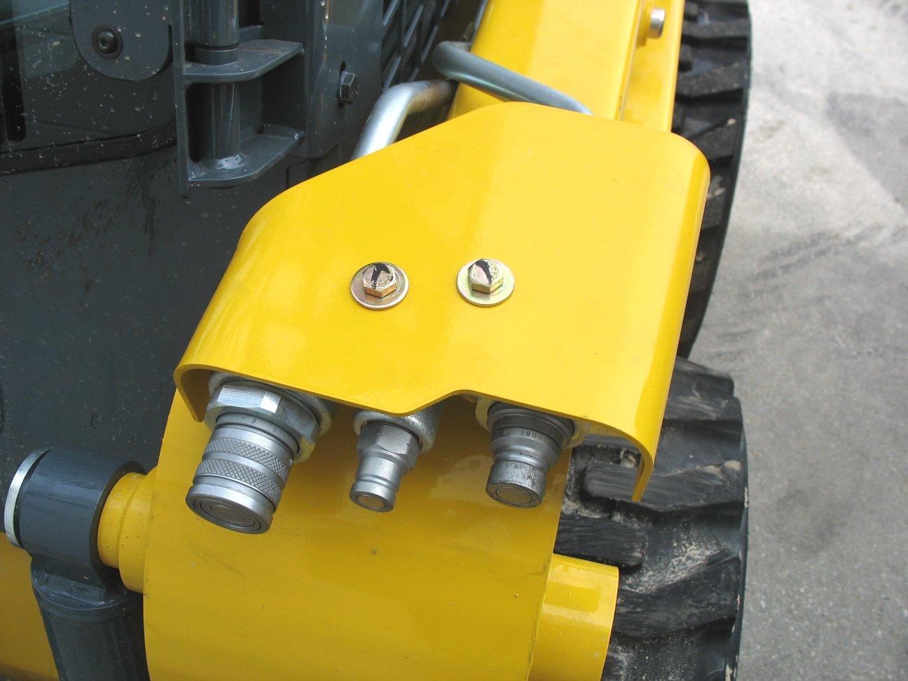
Auxiliary Hydraulic Couplers
Auxiliary hydraulic couplers (Figure 47) are located on top of the lift arm on the left side.
Note: Cover (G) is not present on all machines.
Auxiliary Hydraulics Control
Rocker switch (F, Figure 48) controls the direction and amount of auxiliary hydraulics flow.
Auxiliary hydraulics control is proportional: the farther switch (F)is moved from center, the higher the flow through the auxiliary circuit. Flow direction is reversed when rocker switch (F)is moved in the opposite direction.
To latch continuous auxiliary hydraulic flow, hold the rocker switch (F) in either direction and push the trigger button (G). When the rocker switch and trigger are released, continuous flow should be enabled.
Note: Continuous flow amount is controlled using engine speed.
To cancel continuous flow, either push trigger button (G) or move rocker switch (F) in either direction.
Chapter 5 Operation
Before Starting the Engine
Warning
Before starting the engine and operating the machine:
•Review and comply with all safety recommendations in the Safety chapter of this manual.
•Know how to stop the machine before starting it.
Fuel tank filled?
Engine oil level correct?
Check
Hydraulic system oil level correct?
Engine coolant level correct?
Windshield washer reservoir filled?
Grease fittings properly lubricated?
V-belt condition good/tension adjustment correct?
Tires properly inflated/tire condition good?
Lights, signals, indicators, warning lights, indicators and horn operating properly?
Windows, lights and steps clean?
Attachment securely fastened to hitch?
Overall machine condition (including attachments) for bends, cracks, broken, loose or missing parts, etc.
Engine cover securely closed and latched?
Rags, tools, debris and other loose objects removed? (check especially after maintenance)
Approved warning triangle, hazard warning light and first aid kit in the machine?
Perform safety interlock system test
Seat position correctly adjusted?
Seat belt fastened?
•Fasten and properly adjust the seat belt(s) and lower the operator restraint bar.
Before starting the engine and running the machine, refer to “SAFETY EQUIPMENT” starting on page29 and “Indicators and Controls” starting on page33. Become familiar with the safe operation of the machine and the various operating controls, indicators and safety devices on the machine.
Operational Checks
Pre-Start Checks
Complete the following checks before starting the engine and using the machine. Correct/repair any problems before using the machine.
Refer To:
“Adding Fuel” on page88.
“Checking Engine Oil Level” on page87.
“Checking Hydraulic Oil Level” on page92.
“Checking Coolant Level” on page91.
“Windshield Washer Reservoir” on page99.
“General Lubrication” on page84.
“V-Belt Maintenance” on page91.
“Tires” on page95.
“Control Keypad” on page34, “Control Keypad” on page34.
“Connecting Attachments” on page64.
See “Safety Interlock System Test” on page30.
“Operator’s Seat” on page29.
“Seat Belt” on page29.
Checks During Operation
Table 12: Checks During Operation
Check
After Starting the Engine/During Operation
Complete the following checks after starting the engine and during operation.
Refer To:
Engine oil pressure and charge indicator lights not on?
“Control Keypad” on page34. Parking brake released after starting engine and before operating machine?
“Control Keypad” on page34. Perform restraint bar safety interlock system test. See “Restraint Bar Test” on page31. Steering operating properly?
Coolant temperature indicator light not on?
“Controls” on page42. Engine exhaust excessively smoky?
Anyone hazardously close to the machine?
When Driving on Public Roads
Attachments in transport position?
“Attachment Transport Position” on page63.
Cab Entry and Exit
Use only steps (A, Figure 49) and handles (B) on the machine when entering/exiting. Keep the steps and the handles clean to ensure a secure hold at all times. Never use the controls as hand holds. Remove dirt (oil, grease, earth, snow and ice) from handles (B), steps (A) and your shoes before entering the cab.
Always face the machine when entering/exiting. When entering/exiting the cab. Do not jump on or off the machine. Never climb onto or exit a moving machine.
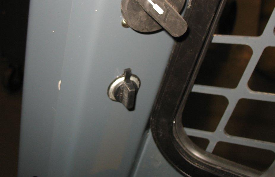
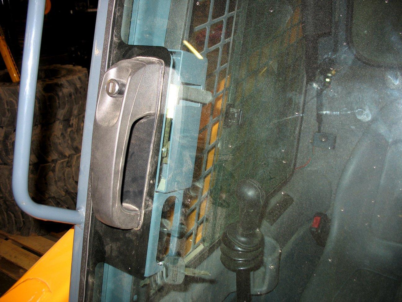
Operate the door latch inside the cab using lever (D, Figure 51) located along the interior door frame.
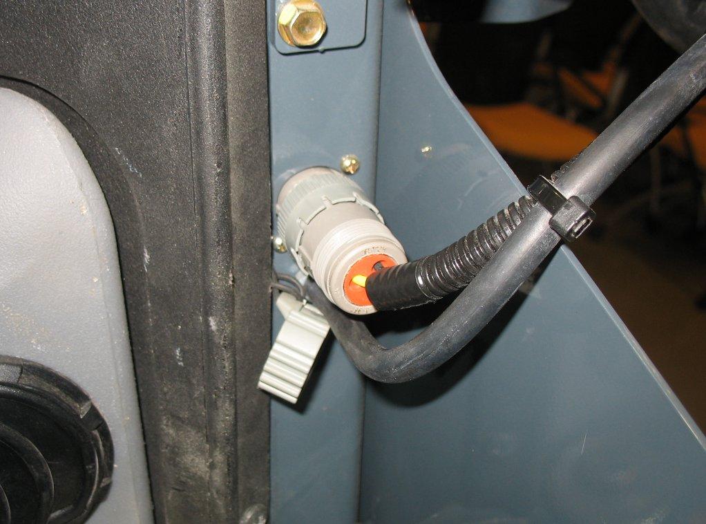
Important: If the door is removed for any reason, make sure to re-connect the door electrical connection (E, Figure 52) when the door is replaced.
Opening/Closing the Cab Door (Option)
Operate the door latch outside the cab using button (C, Figure 50) on the exterior door handle.
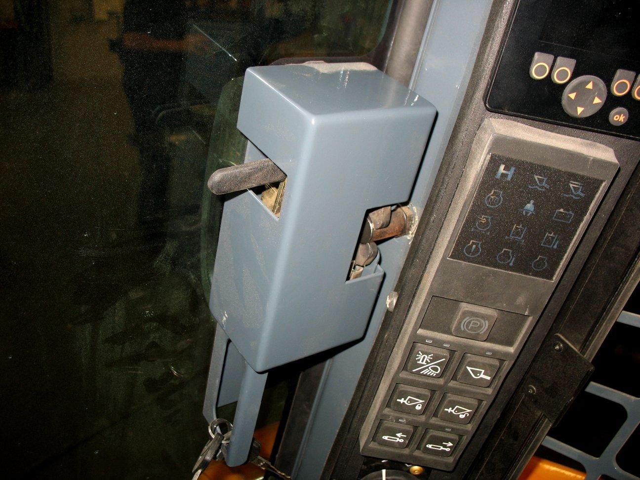
Lock/unlock the door using the ignition key in the key slot in button (C).
Operating the machine with the door electrical connection (E) disconnected can result in damage to the machine not covered under warranty.