19 minute read
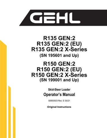
Water Separator Maintenance


NEVER service the fuel system while smoking, while near an open flame, or if the engine is hot.
Important: Water in the fuel system can cause severe engine damage. Drain water from the fuel filter/water separator whenever water is present.
Inspect the water separator daily, or every day before using the machine.
1.Perform the “Mandatory Safety Shutdown Procedure” on page9.
2.Wait until the engine has cooled.
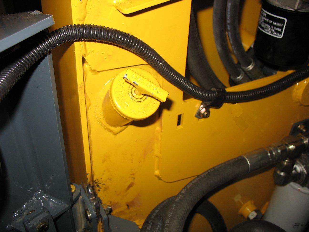
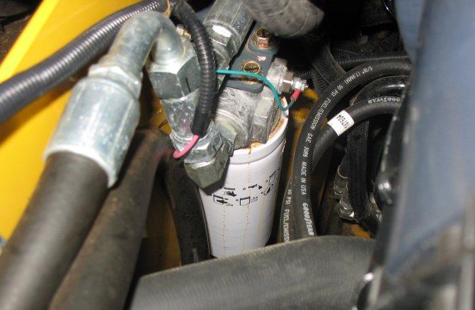
3.Inspect the water separator (Figure 96) for the presence of water:
•If the indicator ring (M) is at the bottom of the cup, no action is required.
•If the indicator ring (M)is floating off the bottom of the cup, water is present and needs to be drained.
4.If water needs to be drained, position a suitable collection container underneath the water separator drain.
5.Turn the fuel valve lever (V) on the water separator to the OFF position.
6.Loosen drain plug (N) at the bottom of the water separator. Allow water to drain until indicator ring falls to the bottom of the cup.
7.Tighten drain plug (N) and discard fuel/water according to environmental laws.
Important: Dispose waste fuel according to environmental laws. DO NOT pour fuel onto the ground or down a drain.
8.Turn the fuel valve lever (V) on the water separator to the ON position.
9.Prime the fuel system by turning the ignition key to the ON position without starting the engine for 30 seconds. Repeat this step 3 times to ensure the fuel system is completely primed.
Caution
Do not use the starter motor to crank the engine to prime the fuel system. Damage to the engine starter motor, coils, pinion/ring gear could result.
10.Start the engine and check for leaks.
Changing Water Separator Filter
Warning
NEVER service the fuel system while smoking, while near an open flame, or if the engine is hot.
1.Perform the “Mandatory Safety Shutdown Procedure” on page9.
2.Wait until the engine has cooled.
3.Turn the fuel valve lever (V, Figure 96) on the water separator to the OFF position.
4.Unscrew the separator bowl from the housing and pull down on the existing filter to release it from the housing.
5.Install a new filter and reinstall the bowl.
6.Turn the fuel valve lever (V) on the water separator to the ON position.
7.Prime the fuel system by turning the ignition key to the ON position without starting the engine for 30 seconds. Repeat this step 3 times to ensure the fuel system is completely primed.
Caution
Do not use the starter motor to crank the engine to prime the fuel system. Damage to the engine starter motor, coils, pinion/ring gear could result.
8.Start the engine and check for leaks.
Changing Fuel Filter
Warning
NEVER service the fuel system while smoking, while near an open flame, or if the engine is hot.
Important: Change the fuel filter every 500 hours of operation.
1.Perform the “Mandatory Safety Shutdown Procedure” on page9.

2.Wait until the engine has cooled.
3.Turn fuel valve lever (V, Figure 97)on the water separator to the OFF position.
Engine Air Cleaner
Important: Failure to follow proper air filter servicing instructions could result in catastrophic engine damage.
4.Remove the fuel filter (W, Figure 98), using a filter wrench if necessary. Carefully clean the filter head mounting surface with a clean cloth.
5.Apply a coating of clean diesel fuel on the new fuel filter gasket. Install the filter and tighten 3/4 rotation past the point where the gasket contacts the filter head.
6.Turn fuel valve (V, Figure 97) on the water separator to the ON position.
7.Prime the fuel system by turning the ignition key to the ON position without starting the engine for 30 seconds. Repeat this step 3 times to ensure the fuel system is completely primed.
Caution
Do not use the starter motor to crank the engine to prime the fuel system. Damage to the engine starter motor, coils, pinion/ring gear could result.
8.Start the engine and check for leaks.
Do not operate the engine without the air cleaner components installed or damage to the engine could occur.
Check the air cleaner intake hose and clamps, and the mounting bracket hardware daily to be sure they are properly tightened. Check, and if necessary replace, the engine air filter after every 250 hours of use, or every 6 months, or if the filter is damaged, oil- or soot-laden.
Be sure the air cleaner intake hose, clamps and mounting bracket hardware are properly tightened.
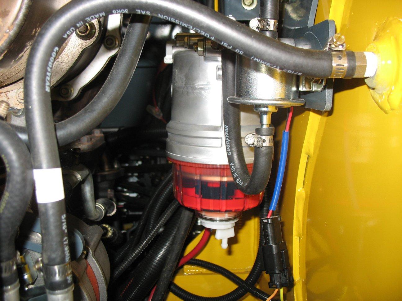
Changing Air Filter Elements
1.Perform the “Mandatory Safety Shutdown Procedure” on page9.
2.Wait until the engine has cooled.
3.Unlatch clamps (J, Figure 99) on the air cleaner housing and remove the air filter cover (L).
4.Clean debris from inside the air cleaner housing and air filter cover.
5.Carefully remove the outer filter element (G).
6.Clean dirt from inside the air filter housing (M).
Important: To prevent debris from entering the engine intake manifold, do not remove inner filter element (H) while cleaning the inside of the housing.
7.Remove inner filter element (H) only if it needs replacement.
8.Check the inside of the housing for damage.
9.If applicable, install a new inner filter element (H). Make sure the sealing surfaces are clean and the new element is properly seated.
10.Install a new outer filter element (G). Make sure the sealing surfaces are clean and the new element is properly seated.
11.Replace air filter cover (L). Latch clamps (J). Make sure the cover is tightly secured and is seated properly in the housing.
12.Check the air cleaner intake hose, clamps and mounting bracket hardware are properly secured and tightened.
DPF Service (DPF Models)
DPF soot filter replacement is required when the DPF (Diesel Particulate Filter) Service Screen (Figure 100) displays.
Cooling System
Important: Check the cooling system every day to prevent overheating, loss of performance or engine damage.
Checking Coolant Level
1.Park the machine on a level surface.
2.Perform the “Mandatory Safety Shutdown Procedure” on page9.
3.Wait until the engine has cooled.
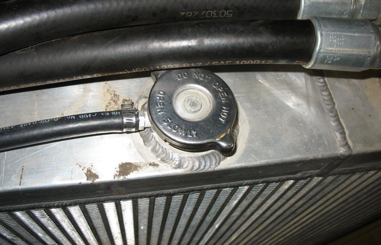
Do not remove radiator cap when the coolant is hot. Serious burns could result.
Note: Contact your dealer when the DPF Service screen displays.
V-Belt Maintenance
1.Perform the “Mandatory Safety Shutdown Procedure” on page9.
2.Wait until the engine has cooled.
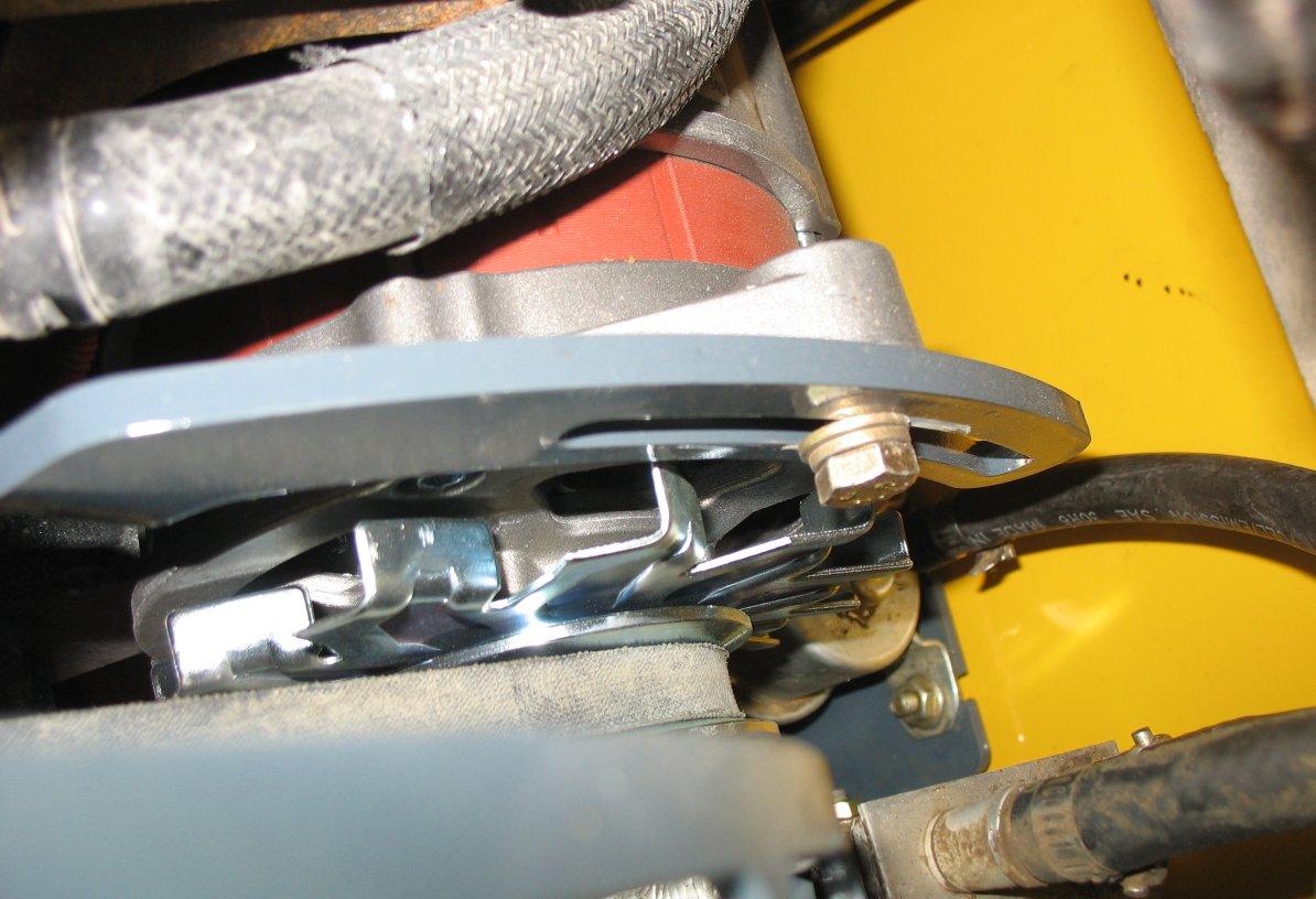
3.Inspect V-belt (F, Figure 101) for damage. If damaged, have belts replaced by an authorized repair shop.
4.Press on V-belt (F) mid-way between pulleys to check deflection. The belt should not deflect more than 8 mm (5/ 16 in.).
5.If deflection is more than 8 mm (5/16 in.): Loosen adjustment bolt (G) and rotate alternator (E) outward until V-belt tension is correct. Tighten bolt (G) and re-check Vbelt tension.
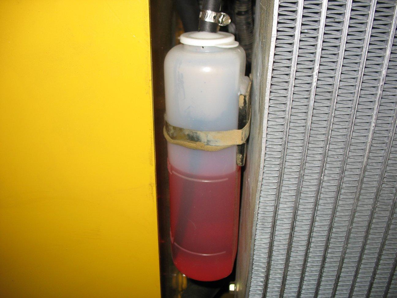
4.Check the coolant level in the expansion reservoir (R, Figure 102). Coolant level must be between the full (T)and low (S) marks on the expansion reservoir. Add coolant to the expansion reservoir as required.
Important: The coolant system is specifically designed for coolant level top-off only through the expansion reservoir. Do not add coolant directly to the radiator.
Note: Use a low-silicate ethylene glycol-based coolant, mixed with quality water and supplemental coolant additives (SCAs) suitable for heavy-duty diesel engines. See “Fluid Capacities/ Lubricants” on page115, “Coolant Compound Mixtures” on page118 and the engine operation manual for additional information.
Cleaning Radiator Fins
The radiator fins can become blocked during use which will lead to reduced cooling function and engine overheating. Clean the radiator cooling fins after every 250 hours or 6 months of operation, whichever occurs first.
1.Perform the “Mandatory Safety Shutdown Procedure” on page9.
2.Wait until the engine has cooled.
3.Open the rear door. Lift the engine cover.
4.Clean the radiator fins by blowing air/water through the fins from the rear of the radiator, toward the engine.
Important: Use caution! High pressure air/water can damage radiator fins.
Draining/Flushing Cooling System
1.Perform the “Mandatory Safety Shutdown Procedure” on page9.
2.Wait until the engine has cooled. Do not remove radiator cap when the coolant is hot. Serious burns could result.
3.Slowly loosen radiator cap (P, Figure 103) and allow pressure to escape. Remove cap.
4.Position a suitable collection container, with a minimum capacity of 19 L (4 gals.) underneath the radiator.
9.Start and run the engine until it reaches operating temperature.
10.Check the coolant level according to “Checking Coolant Level” on page91.
Hydraulic System
Never use your hands to search for hydraulic fluid leaks; use a piece of paper or cardboard to find leaks. Escaping fluid under pressure can be invisible and can penetrate the skin, causing serious injury. If any fluid is injected into your skin, see a doctor at once. Injected fluid MUST be surgically removed, or gangrene may result.
Checking Hydraulic Oil Level
5.Remove radiator drain plug (X, Figure 104) underneath the radiator and allow the coolant to drain into the container.
Important: Dispose waste coolant according to environmental laws. DO NOT pour coolant onto the ground or down a drain.
6.Replace the drain plug (X) and tighten securely.
7.Fill the radiator with coolant.
Note: Use a low-silicate ethylene glycol-based coolant, mixed with clean water and supplemental coolant additives (SCAs) suitable for heavy-duty diesel engines. See “Fluid Capacities/ Lubricants” on page115, “Coolant Compound Mixtures” on page118 and the engine operation manual for additional information.
8.Reinstall radiator cap and tighten securely.
Check the hydraulic oil level daily before starting the machine, or after every ten hours of use.
1.Perform the “Mandatory Safety Shutdown Procedure” on page9.
2.Wait until the engine has cooled.
3.Open the engine compartment according to “Engine Access” on page86.
4.Check the level of the hydraulic oil:
• Model R150: Locate sight gauge (Y, Figure 105) in the left engine compartment wall. The oil level should be in the middle (A) of the sight gauge.
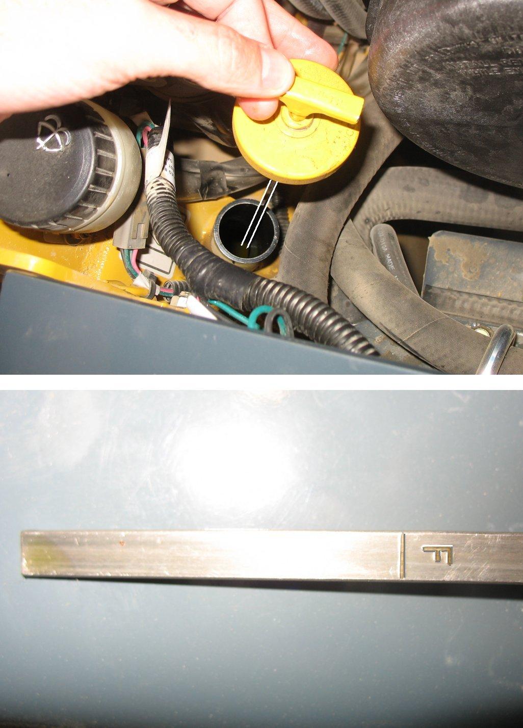
• Model R135: Remove the hydraulic tank filler/dipstick cap (H).
Important: Slowly remove the hydraulic oil fill cap (H). Allow the pressure to escape before completely removing the cap.
Wipe dipstick (X) with a clean cloth and replace it in the filler neck. Push it in until cap (H) is fully seated. Remove the dipstick again. The oil level should be at the (F)mark.
5.If the hydraulic oil level is low, remove the hydraulic tank filler cap (H, Figure 106), located in the left engine compartment wall.
Important: Slowly remove the hydraulic oil fill cap (H). Allow the pressure to escape before completely removing the cap.
6.Add hydraulic fluid if required. See “Fluid Capacities/ Lubricants” on page115 for proper hydraulic oil grade and type.
Important: Do not mix different types/grades of hydraulic fluids.
7.Reinstall hydraulic tank filler cap (H) and tighten securely.
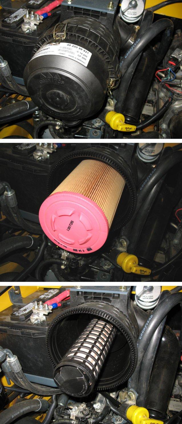
Changing Hydraulic Oil Filter
1.Perform the “Mandatory Safety Shutdown Procedure” on page9.
2.Wait until the engine has cooled.
3.Open the engine compartment according to “Engine Access” on page86.
4.Place oil pan under the machine to catch the oil.
5.Unscrew and remove hydraulic oil filter (L, Figure 107).
Important: T-Bar machines have an additional second hydraulic oil filter (charge filter) on the left side of the chassis, beneath the ROPS/FOPS that should be changed with the main hydraulic filter.
6.Clean the surface of the filter housing where the element seal contacts the housing. Put clean oil on the rubber gasket of the new filter (L).
7.Install and tighten the filter (L) 3/4 of a rotation past the point where the gasket contacts the filter head.
Changing Hydraulic Oil
The hydraulic oil must be replaced if it becomes contaminated, after major repairs, and after 1000 hours or one year of use.
1.Perform the “Mandatory Safety Shutdown Procedure” on page9.
2.Wait until the engine has cooled.
3.Open the engine compartment according to “Engine Access” on page86.
4.Slowly loosen hydraulic oil filler cap (H, Figure 106).
5.Position a waste oil collection container with a capacity of at least 60 L (16 gals.) underneath the hydraulic oil reservoir.
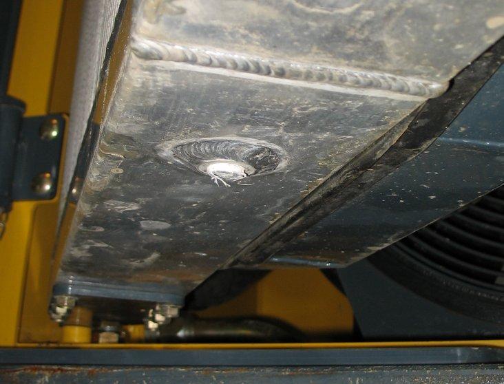
Note: The hydraulic reservoir drain plug is accessed from underneath the machine at the left rear corner.
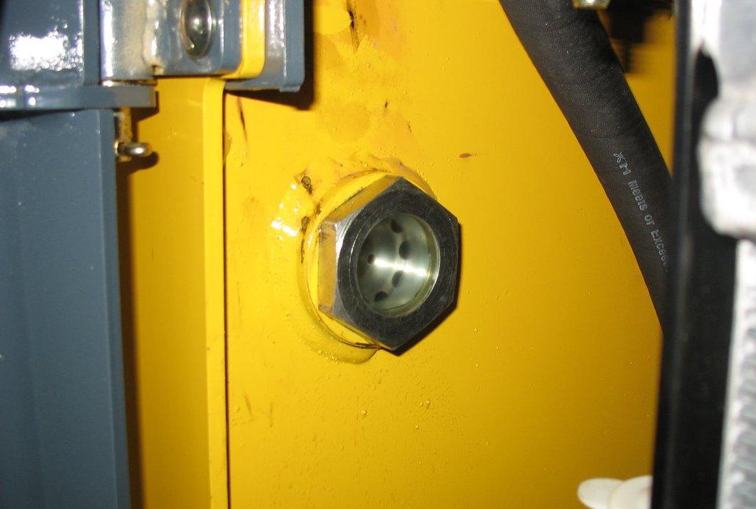
6.Remove the hydraulic reservoir drain plug (O, Figure 108) and allow the oil to drain completely.
Important: Always dispose of hydraulic oil according to environmental laws or take to a recycling center for proper disposal. DO NOT pour onto the ground or down a drain.
7.Unscrew and remove the hydraulic oil filter (L, Figure 107).
8.Clean the surface of the filter housing where the element seal contacts the housing. Put clean oil on the rubber gasket of the new filter (L, Figure 107).
9.Install and tighten the filter (L, Figure 107) 3/4 of a rotation past the point where the gasket contacts the filter head.
10.Reinstall and tighten drain plug (O, Figure 108).
11.Remove hydraulic oil filler cap (H, Figure 106) and fill the hydraulic oil reservoir until the oil level is correct (Y, Figure 105).
Important: See “Fluid Capacities/Lubricants” on page115 for proper hydraulic oil grade and type. Hydraulic oil capacity listed is approximate. Always verify proper oil level. See to “Checking Engine Oil Level” on page87.
12.Start the engine and operate the drive, lift and tilt controls.
13.Stop the engine and check for leaks at the filter and reservoir drain plug.
14.Check the fluid level and add fluid if needed.
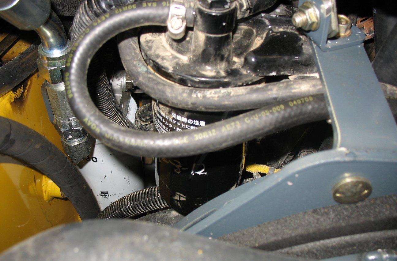
Hydraulic Hose Maintenance
Warning
Hydraulic hoses and connections must be inspected by a trained technician before the first use of the machine, and at least annually thereafter, for leaks and/or damage.
Leakages and damaged pressure hose/lines must be immediately repaired or replaced by an authorized service center.
Never use your hands to check for suspected hydraulic leaks. Always use a piece of wood or cardboard.
Leaks from hydraulic hoses or pressurized components can be difficult to see, but pressurized oil can have enough force to pierce the skin and cause serious injury.
Obtain immediate medical attention if pressurized oil pierces the skin. Failure to obtain prompt medical assistance could result in gangrene or other serious damage to tissue.
Always relieve hydraulic system pressure before performing any maintenance on the machine. Do not tighten leaking connections when the hydraulic system is under pressure.
Never weld or solder damaged or leaking pressure lines and/or screw connections. Always replace damaged hydraulic components.
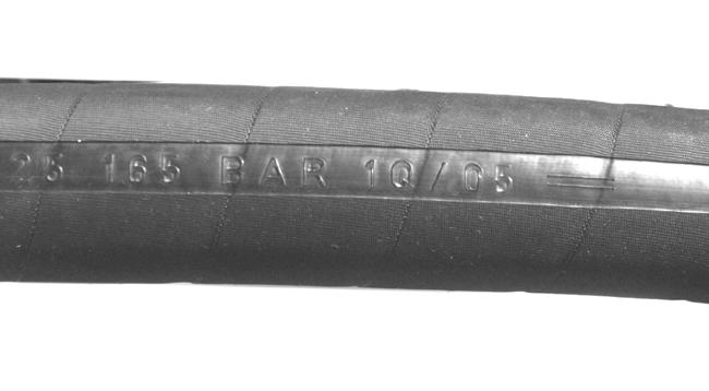
Hydraulic hoses must be replaced every six years from the date of manufacture, even if they do not appear damaged. The date of manufacture (month or quarter and year) is indicated on hydraulic hoses. See Figure 109.
Chaincases
The chaincase contains the drive sprockets and drive chains. There are two plugs in each chaincase. One is to drain the oil and the other is to check the oil level. Refer to the “Maintenance Schedules” on page80 for change intervals. See “Fluid Capacities/Lubricants” on page115 for information on recommended type and amount of oil.
Drive Motors
The travel drive motors do not require periodic lubrication oil changes because they are lubricated by the oil in the hydraulic system.
Checking and Adding Chaincase Oil
1.Park the machine on a level surface.
2.Perform the “Mandatory Safety Shutdown Procedure” on page9.
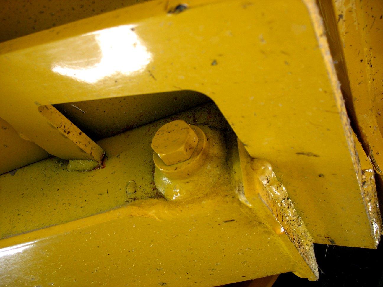
3.Remove check/ fill plug (S, Figure 110) from each chaincase housing. If the oil can be reached with the tip of your finger, the oil level is adequate.
4.If the level is low, add oil through the check plug until the oil level reaches the edge of the hole. Reinstall the check/fill (S)plug.
Changing Chaincase Oil
1.Raise the rear of the machine to aid in draining the chaincases.
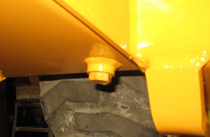
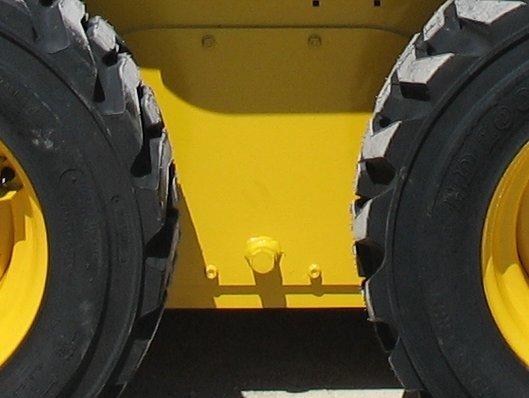
2.Remove drain plugs (T, Figure 111)on both chaincases and drain the oil into a suitable container(s).
Note: Drain plugs (T) are located inside the tie-down brackets at the bottom front of the machine.
3.Reinstall and tighten drain plugs (T).
4.Refill the chaincases according to “Checking and Adding Chaincase Oil” on page94.
Drive Chain Tension
Drive chains are located in the chaincase on each side of the machine. See “Maintenance Schedules” on page80 for chain tension check interval.
Checking Chain Tension
1.Raise the machine according to the “Lifting the Machine” on page85.
2.Rotate each tire by hand. The proper amount of chain defection should be 3-25 mm (1/8-1 in.) forward and rearward tire movement. If the chain defection is more than 25 mm (1 in.) or less than 3 mm (1/8 in.) in either direction, the chains should be adjusted.
Adjusting Chain Tension
1.Raise the machine according to the “Lifting the Machine” on page85.
2.Remove the wheel from the axle to be adjusted.
3.Loosen (but DO NOT remove) the bolts holding the axle to the chaincase.
4. Front Chain Tension – To tighten the front chain, move the front axle assembly toward the front of the machine. To loosen the chain, move the front axle assembly toward the rear of the machine.
Rear Chain Tension – To tighten the rear chain, move the rear axle assembly rearward. To loosen the chain, move the rear axle assembly toward the front of the machine.
5.After proper tension is achieved, tighten the bolts. Important: Be careful not to over-tighten the drive chains. Over-tightening will cause premature drive chain and axle sprocket wear.
6.Reinstall the wheel.
7.Repeat this procedure for any other axle requiring adjustment.
8.Lower the machine according to the “Lowering the Machine” on page86.
Seat and Restraint Bar Switches
Electrical switches in the seat and restraint bar must be closed (operator sitting in the seat and restraint bar lowered) and the auxiliary hydraulics must be in neutral to complete the circuit and start the engine.
Bucket Cutting Edge
The bucket cutting edge should be replaced when it is worn to within 25 mm (1 in.) of the bucket body.
Wheel Nuts
Wheel nut torque must be checked before initial operation and every two hours until the wheel mounting hardware torque stabilizes at the following recommended settings:
• Model R135: 161-175 Nm (120-130 lb.-ft)
• Models R150: 244 Nm (180 lb.-ft)
Check wheel nut torque every 250 hours thereafter. When tires are removed and replaced, this procedure must be repeated.
Tires
Rear tires usually wear faster than the front ones. To keep tire wear even, rotate the tires from front to rear and rear to front. It is important to keep the same size tire on both sides of the machine to prevent excessive wear on tires or other damage. If different sizes are used, each tire will be turning at different speeds, causing excessive wear.
The tread bar of all tires must face the same direction.
Mounting Tires
WARNING
Servicing tires can be dangerous. When possible, trained personnel should service and mount tires. To avoid possible death or serious injury, follow the safety precautions below.
Important: The tread bars of all tires should point the same direction.
•Be sure the rim is clean and free of rust.
•Lubricate the tire beads and rim flanges with a soap solution. Do not use oil or grease.
•Use a clip-on tire chuck with remote hose and gauge, allowing you to stand clear while inflating the tire. Do not place your fingers on the tire bead or rim during inflation.
•Never inflate beyond 240 kPa (35 psi) to seat the beads. If the beads have not seated by the time the pressure reaches 240 kPa (35 psi), deflate the assembly, reposition the tire on the rim, lubricate both parts and re-inflate. Inflation pressure beyond 240 kPa (35 psi) with unseated beads may break the bead or rim with explosive force sufficient to cause death or serious injury.
Checking Tire Pressure
Table 18: Tire Inflation Pressures
•After seating the beads, adjust the inflation pressure to the recommended operating pressure.
•Do not weld, braze or otherwise attempt to repair and use a damaged rim.
Correct tire pressure should be maintained for all tires to enhance operating stability and extend tire life. Refer to the above chart for the proper inflation pressure.
When installing tires, be sure they are the same size and style on both sides of the machine. Always replace tires with the same size as the original equipment.
Electrical System
Warning
Inspect and check the machine’s electrical equipment at regular intervals. Defects, such as loose connections or scorched cables must be repaired before using the machine.
Only use proper, original equipment fuses with the specified current rating. Turn off the machine immediately if there are any problems with the electrical system.
Work on the machine’s electrical system must be performed only by a trained technician.
Fuses, Relays and Diodes
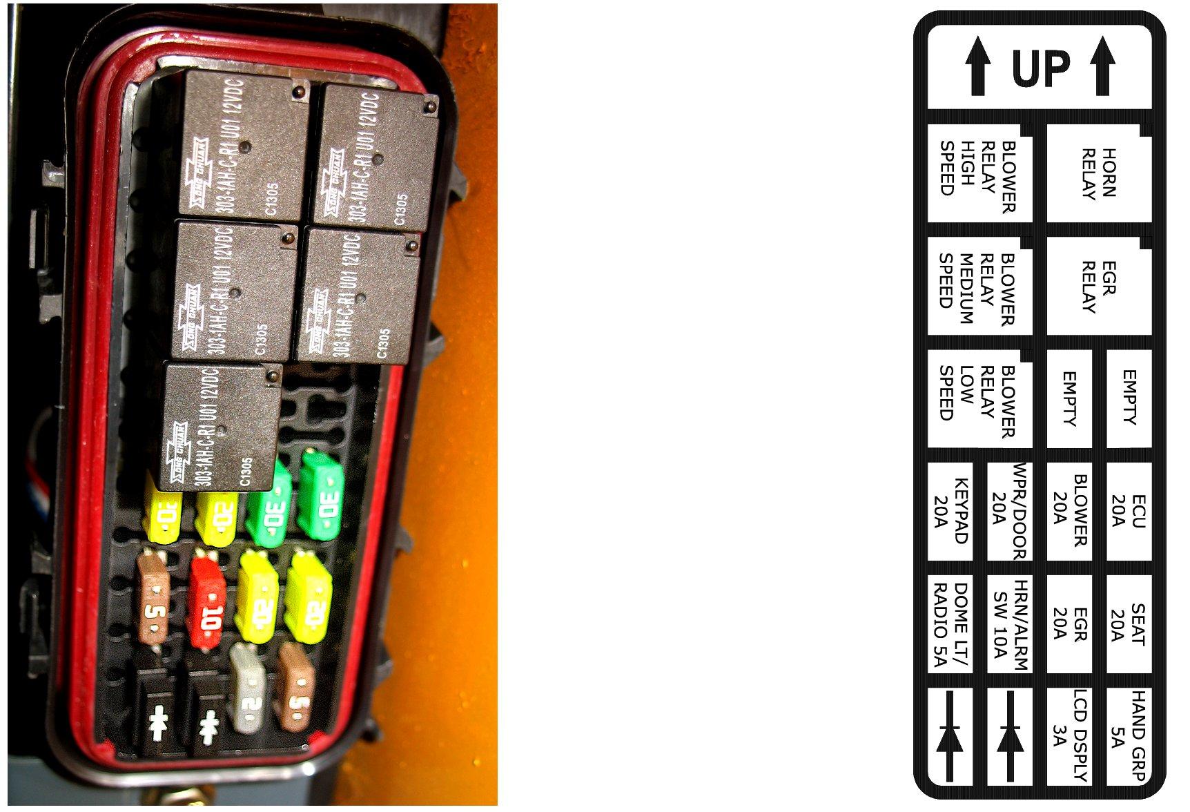
Important: Blown fuses indicate electrical system malfunctions. Determine what caused the fuse to blow and repair the problem before replacing the fuse.
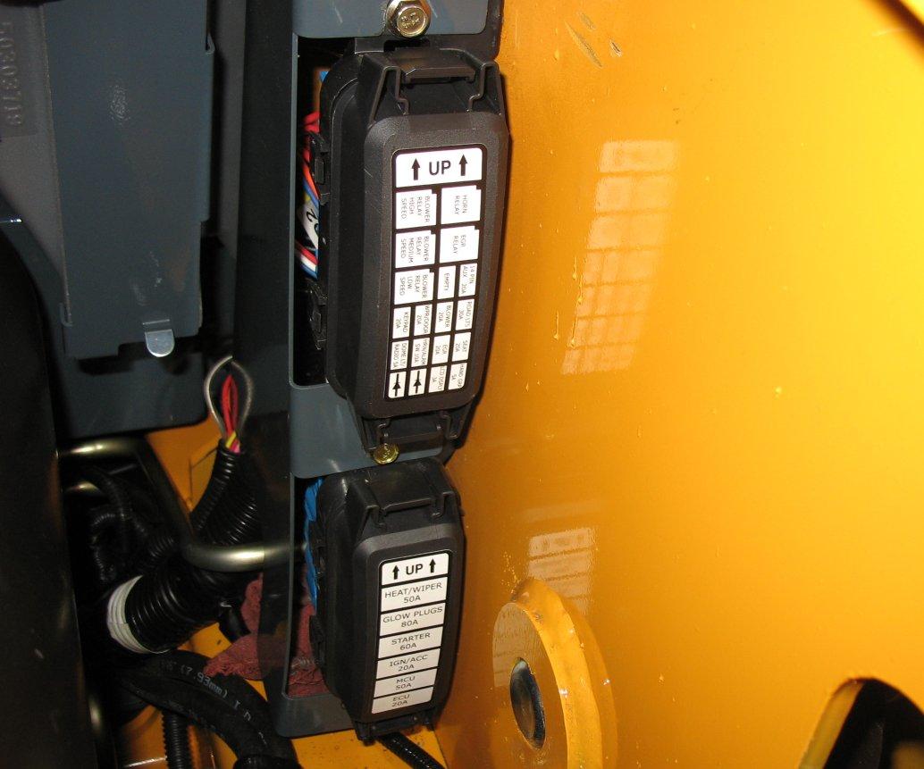
The fuse, relay and diode boxes are located in the engine compartment, just behind the cab, on the right side of the machine.
AHigh-speed cab blower fan relay
CMedium-speed cab blower fan relay
Gas Recirculation (EGR) relay ELow-speed cab blower fan relay
Table 20: Fuse Locations (Figure 113)
FuseRated Current (A) Circuit FuseRated Current (A) Circuit
F20A Control Keypad
H20A Cab blower fan
J5A Dome light, Radio
G20A
I20A
K10A
L20A Exhaust Gas Recirculation (EGR)M20A
N3A Electronic display LCD
Table 21: Diode Locations (Figure 113)
O5A
Windshield wiper, Door
Electronic Control Unit (ECU) Note: if required
Horn, Alarm
Operator’s seat switch/optional air suspension
Hand control buttons
Diode Circuit Diode Circuit
P Ignition
Q EGR Valve (Tier 4)
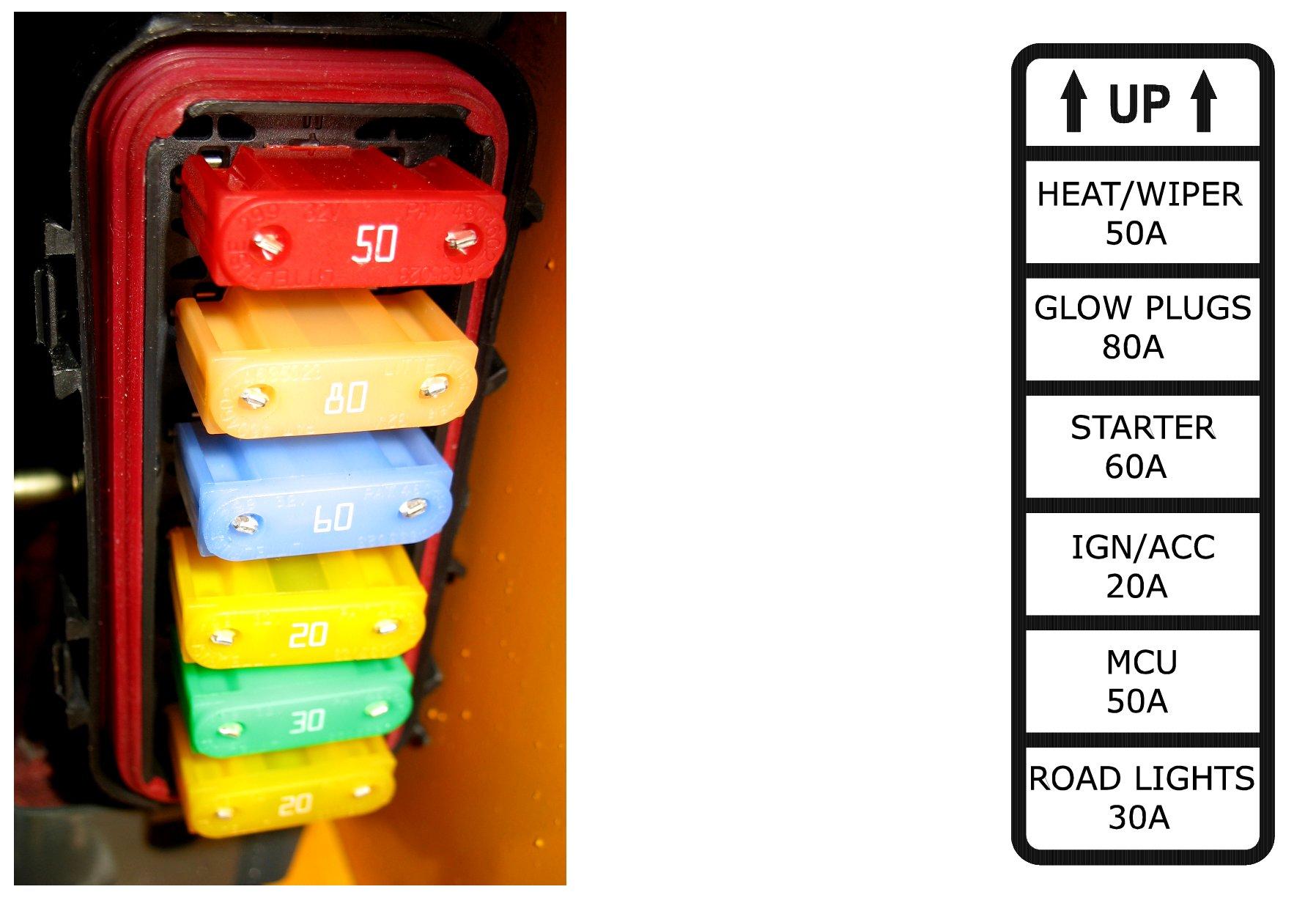
Table 22: Maxi Fuse Locations (Figure 114)
FuseRated Current (A) Circuit FuseRated Current (A) Circuit
R50A Cab heat, Wiper
T60A Starter
V50A Micro Controller Unit (MCU)
S80A Glow Plugs
U20A Ignition, Accessories
W30A Road lights
Before servicing the battery or electrical system, be sure the battery disconnect switch (if equipped) is in the OFF position. If not equipped with a disconnect switch, disconnect the ground (-) terminal from battery.
The battery is a 12-volt, wet-cell battery. To access the battery, remove front floor panel.
The battery top must be kept clean. Clean it with an alkaline solution (ammonia or baking soda and water). After foaming has stopped, flush the battery top with clean water. If the terminals and cable connection clamps are corroded or have a build-up, disconnect the cables and clean the terminals and clamps with the same alkaline solution.
Windshield Washer Reservoir
The windshield washer reservoir (E, Figure 115) is located inside the engine compartment. Check the windshield washer reservoir level daily before starting the machine and fill if necessary.
Important: Fill the windshield washer fluid reservoir with clean tap water or windshield washer fluid only. If using tap water, add a cleaning agent if required and/or antifreeze in cold weather.
Long-Term Storage
If storing the machine for a long period (longer than 2 months), perform the procedures in this section.
Explosive gas is produced while a battery is in use or being charged. Keep flames or sparks away from the battery area. ALWAYS charge the battery in a well-ventilated area.
Never lay a metal object on top of a battery, because a short circuit can result.
Whenever the battery is removed, be sure to disconnect the negative (-) battery terminal connection first.
Battery acid is harmful on contact with skin or fabrics. If acid spills, follow these first-aid tips:
1.Immediately remove any clothing on which acid spills.
2.If acid contacts the skin, rinse the affected area with running water for 10 to 15 minutes.
3.If acid contacts the eyes, flood the eyes with running water for 10 to 15 minutes. See a doctor at once. Never use any medication or eye drops unless prescribed by the doctor.
4.To neutralize acid spilled on the floor, use one of the following mixtures: a.0.5 kg (1 lb.) of baking soda in 4 L (1 gal.) of water. b.0.5 L (1 pt.) of household ammonia in 4 L (1 gal.) of water.
Before Storage
1.Wash the entire machine. Treat vinyl surfaces in the operator’s compartment with a vinyl protectant.
2.Perform all steps for long-term engine storage according to the engine operation manual.
3.Check tire pressure; adjust to correct pressure, if necessary. See “Tires” on page95.
4.Lubricate all grease fittings. See “General Lubrication” on page84.
5.Check all fluid levels and top-off as necessary.
6.Add a fuel stabilizer to the fuel system according to the fuel supplier’s recommendations.
7.If the machine is so equipped, turn the battery disconnect switch to the off position. See “Battery Disconnect Switch” on page52.
8.Remove and fully charge the battery. Store the battery in a cool, dry location.
9.If the machine will not be operated for a month or longer, apply grease to all exposed hydraulic cylinder rod areas or retract all cylinders so rod exposure is minimized. Apply grease to any remaining rod areas.
10.Protect against extreme weather conditions such as moisture, sunlight and temperature. Fill the engine coolant system with the proper mix of antifreeze and water as required for expected temperatures according to “Coolant Compound Mixtures” on page118.
Important: Contact your dealer for additional storage preparation information if the machine will be stored in an environment where temperatures could range below -42°C (44°F), and/or above 49°C (120°F).
After Storage
1.Replace and re-connect the battery.
2.If the machine is so equipped, turn the battery disconnect switch to the on position. See “Battery Disconnect Switch” on page52.
3.Check tire pressure; adjust to correct pressure, if necessary. See “Tires” on page95.
4.Perform all steps for returning the engine to service according to long-term engine storage section in the engine operation manual.
5.Check V-belt tension. See “V-Belt Maintenance” on page91.
6.Check all fluid levels and top-off as necessary.
7.Start the engine. Observe all indicators. If all indicators are functioning properly and reading normally, move the machine outside.
8.When outside, park the machine and let the engine idle for at least 5 minutes.
9.Shut off the engine and walk around machine. Make a visual inspection looking for evidence of leaks.
Final Shutdown / Decommissioning
Important: Dispose of all materials properly. Used oils/fluids are environmental contaminants and may only be disposed of at approved collection facilities. Never drain any oils/fluids onto the ground, dispose of in municipal waste collection containers, or in metropolitan sewer systems or landfills. Check state and local regulations for other material disposal requirements.
If the machine will no longer be used as intended, shutdown, decommission and dispose of it according to the valid regulations.
Before Disposal
1.Shut down the machine according to valid regulations regarding proper shutdown.
2.Park the machine on level, dry ground. Ensure the surface can support the weight of the machine. Ensure the location is protected against access by unauthorized persons.
3.Move the throttle to the low-idle position and allow the engine to cool for approximately 2 minutes.
4.Shut off the engine.
5.Move the lift/tilt and if equipped, the Power-A-Tach® quick attach control(s) to verify that the controls do not cause movement of the lift arm or hitch.
6.Raise the arm rests/safety bars to apply the parking brake and lock out the hydraulic controls.
7.Switch off all electrical switches.
8.Unfasten the seat belt, remove the ignition key and take it with you.
9.Ensure the machine poses no dangers in the place where it is standing.
10.Ensure the machine cannot be operated after shutdown until further disposal.
11.Ensure no environmentally hazardous materials, fluids and/ or fuel can escape the machine.
12.Specifically check for leaks from the engine, the hydraulic system and the coolant system.
13.Remove any dirt and/or debris from the engine compartment, the chassis and the cylinder rod surfaces.
14.Remove the battery.
15.Lock the cab door, the storage compartment, the battery and hydraulic filler compartments and the engine compartment. Remove the key(s) and take it/them with you.
Machine Disposal
Make sure all materials are disposed of in an ecologically sound manner.
Recycle the machine in accordance with the current state of the art at the time of recycling. Observe all accident prevention regulations.
Dispose of all parts at the at the recycling sites specific to the material of the part. Take care to separate different materials for recycling.
Dealer Services
Service of the following components require special tools, skill and knowledge are not part of normal maintenance and are not included in this manual. Service of these components should only be performed by an authorized dealer:
•Engine service not included in this manual:
•Hydrostatic components.
•Hydraulic system pumps.
•Valves.
•Cylinders.
•Electrical components (other than the battery, relays and fuses).