
24 minute read
Changing Attachments


Warning
To prevent unexpected release of the attachment from the hitch, make sure the attachment is fully locked onto the hitch before using the attachment. On manual All-Tach® hitches, rotate the latch levers fully. On Power-A-Tach® hitches, verify that the pin flags are all the way to the outside of the hitch.
Always verify that the locking pins on the hitch are fully engaged down through the holes in the attachment frame before using the attachment. The attachment could fall off if it is not locked on the hitch and could cause serious injury or death.
Connecting Attachments
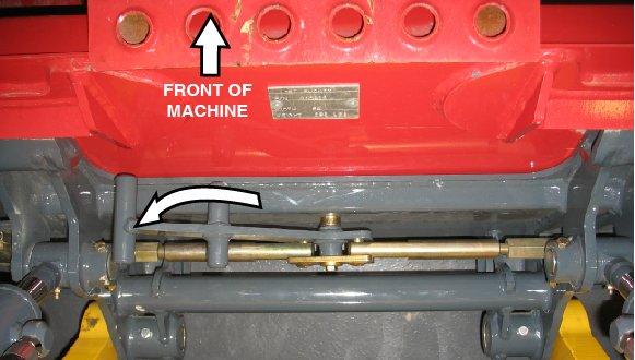
1.In an open, level area, place the attachment lock into the unlocked position (Figure 60):
• All-Tach® system manual hitch: Move hitch lock lever (G) all the way to the right.
Manual Attachment Hitch In Unlocked Condition
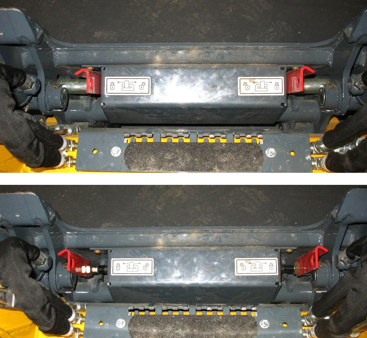
Power-A-Tach® System Quick Attach Hitch In Unlocked Condition
• Power-ATach® system quick attach hitch: Press the PowerA-Tach® system unlock button (I) on the control keypad until safety flags (H) have moved all the way in.
2.Tilt the attachment plate forward and drive the machine straight forward toward the back of the attachment
3.Lower the lift arm so tabs (J) on the top of the attachment plate are aligned just under the hooks on the back of the attachment.
4.Tilt the attachment plate back until tabs (J) on the top of the attachment plate are engaged against the hooks on the back of the attachment.
5.Raise the lift arm slightly until the attachment is hanging from the hooks on the back of the attachment and tabs (J) are firmly inserted into the hooks. Tilt the attachment plate back, if necessary, so the back of the attachment is resting flat against the attachment plate.
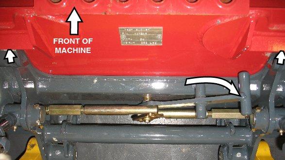
6.Place the attachment lock into the locked position (Figure 61):
• All-Tach® system manual hitch: Perform the “Mandatory Safety Shutdown Procedure” on page9 and move hitch lock lever all the way to the left (G).
Manual Attachment Hitch In Locked Condition
• Power-ATach® system quick attach hitch: Press the PowerA-Tach® system lock button (N) on the control keypad. The safety flags (H) will move to the outside of the hitch.
Note: It is safe to operate the loader with the warming circuit on or off, it won't affect the performance of the loader.
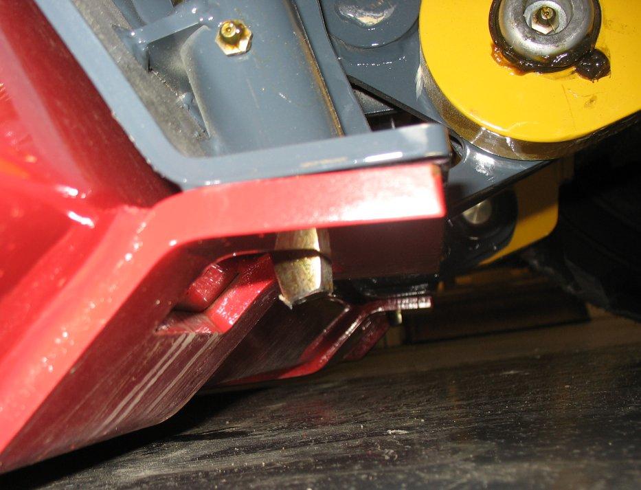
7.Make sure the locking pins (F, Figure 62) are fully engaged down through the holes in the attachment.
Warning
To prevent unexpected release of the attachment from the hitch, be sure the locking lever is rotated all the way to the right (as viewed while facing back at the machine from the front) and the locking pins (F, Figure 62) extend down through the attachment frame.
Locking pins (F) must be fully extended down through the holes in the attachment frame before using the attachment. The attachment could fall off if it is not locked on the hitch and cause serious injury or death.
Important: To check that the attachment is properly installed, tilt the attachment forward slightly, and apply downward pressure to the attachment before using it.
Disconnecting Attachments
Position the attachment so that after disconnecting, the attachment will stand safely and not tip over. Serious injury can occur if an attachment tips over onto a person.
1.Empty the attachment and drive to an open, level area to disconnect the attachment.
2.Lower the attachment to the ground.
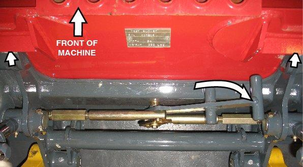
3.Place the attachment lock into the unlocked position (Figure 63):
• All-Tach® system manual hitch: Move hitch lock lever (G) all the way to the right.
• Power-ATach® system quick attach hitch: Press the PowerA-Tach® system unlock button (I) on the control keypad until

Manual Attachment Hitch In Unlocked Condition safety flags (H) have moved all the way in.
4.Lower the lift arm until tabs (J) on top of the attachment plate disengage out of hooks (K) on the back of the attachment.
5.Look behind you for bystanders and obstacles. Drive straight back in reverse away from the attachment.
Connecting Auxiliary Hydraulic Couplings
Important: Connect hydraulically-powered attachment hoses to the auxiliary circuits after the attachment is secured to the hitch.
Disconnect hydraulically-powered attachment hoses from the auxiliary circuits before removing the attachment from the hitch.
1.Empty the attachment and lower it to the ground.
2.Shut off the engine. With the ignition on, but the engine off, move the auxiliary hydraulics control rocker switch (F, Figure 64) on the right T-bar, joystick or hand control back and forth to relieve pressure in the auxiliary hydraulics circuit.
3.Turn off the ignition. Remove the ignition key and take it with you.
4.Raise the restraint bar and exit the machine using the hand holds.
5.Clean the hydraulic connections on the hoses and the connections.
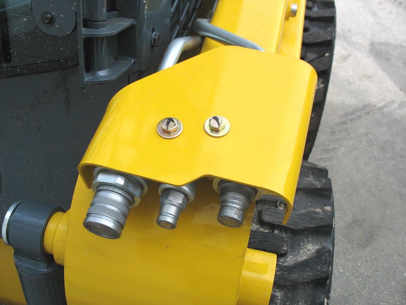
6.Relieve any residual pressure remaining in the auxiliary hydraulics circuit by pushing the attachment coupler firmly into the auxiliary coupler (Figure 65).
Caution
Route the hydraulic hoses so they do not get pinched when the attachment is tilted forward and back. Damaged or burst hydraulic hoses could result.
7.Continue to push the hose connections firmly onto the auxiliary hydraulic connections until they snap into place.
Note: Pressure build-up caused by heat in hydraulic attachments left in direct sunlight can make it difficult to connect the quickcouplers to the fittings on the attachment.
Note: The auxiliary hydraulic couplers are located on the left lift arm. When the auxiliary control switch is activated in either direction, the inside and outside couplers can be “pressure” or “return”, depending on which direction the switch is activated. The smaller center coupler is for the case drain.
Important: Always check hydraulic function of the attachment before use, to make sure the hydraulic hoses have not been installed in reverse.
Disconnecting Auxiliary Hydraulic Couplings
1.Empty the attachment and lower it to the ground.
2.Shut off the engine, but do not turn off the ignition. Move the auxiliary hydraulics control rocker switch (F, Figure 66) on the right T-bar, joystick or hand control back and forth to relieve pressure in the auxiliary hydraulics circuit.
3.Turn off the ignition. Remove the ignition key and take it with you.
4.Raise the restraint bar and exit the machine using the hand holds.
5.Push on the hose connection locking rings until the hose connections release.
Self-Leveling (Option)
Self-leveling automatically keeps the tilt angle of the attachment constant, relative to the ground plane, when the lift arm is raised (A, Figure 67). This feature is especially useful when using pallet forks.
Important: Selfleveling operates only when the lift arm is raised: when the lift arm is lowered (B), selfleveling is not activated.
Note: Self-leveling is activated by default. To deactivate selfleveling, see “SelfLeveling Cancel” on page67.
Self-Leveling Cancel
The self-leveling cancel option allows deactivation of the selfleveling feature when equipped with this option.
To deactivate selfleveling, press the self-level cancel button (E, Figure 68)on the control pad. To restore selfleveling, press button (E) again.
Note: If equipped with this option, self-leveling is activated by default. If the engine is shut off, self-leveling defaults to the activated condition.
Note: Indicator (F) above button (E) is lit when the self-leveling cancel option is on and the self-leveling feature is deactivated. This indicator will light if the unit does not have this installed option.
Using Buckets
Warning
Read the “Safety” section in this manual, starting on page 9, before working with a bucket. Pay special attention to the “During Operation” information, starting on page 11 Always follow the information included in the “Safety” section. Serious injury or death can occur if the safety information is not followed.
Always maintain a safe distance from electric power lines and avoid contact with any electrically charged conductor or gas line. Accidental contact or rupture can result in electrocution or an explosion. Contact the “Call Before You Dig” referral system at 8-1-1 in the U.S., or 888-258-0808 in the U.S. and Canada or proper local authorities for utility line locations before starting to dig.
Make sure the bucket is securely attached to the hitch before starting work. See “Connecting Attachments” on page 64.
Avoid tilting a bucket back when the lift arm is fully raised Material may fall over the rear of the bucket and onto the operator If necessary, fit the rear of the bucket with a guard to prevent material from falling out of the back of the bucket.
50950503/E0521
Always carry the loaded bucket with the lift arm in the transport position. See “Attachment Transport Position” on page63. For additional stability when operating on inclines, always travel with the heavier end of the machine toward the top of the incline.
Make sure you have a good view of the material you are digging, and of the area you will be working in.
Use extreme care when digging around foundations or walls. Never remove material that might compromise a wall or foundation.
Never push the “float” button with the bucket or attachment raised, because this will cause the lift arm to fall.
Caution
Follow the recommendations in “Fields of Application” on page4.
Digging with a Bucket
1.(Figure 69) Approach the digging site with the lift arm slightly raised. Tilt the bucket forward until the cutting edge contacts the ground.
2.Tilt the cutting edge of the bucket down at an angle appropriate for ground hardness.
3.Drive forward slowly, digging into the ground with the cutting edge of the bucket and gradually lower the lift arm.
4.When the bucket is full, raise the bucket and tilt it back and back away from the material.
Always carry the loaded bucket with the lift arm in the transport position. See “Attachment Transport Position” on page63. For additional stability when operating on inclines, always travel with the heavier end of the machine toward the top of the incline.
Loading a Bucket
1.(Figure 70) Lower the bucket to the ground.
2.Tilt the bucket slightly forward so the bucket cutting edge is pointing slightly down into the ground.
3.Drive forward until the bucket is filled with material. Adjust the bucket tilt as needed to remove an even layer of ground and to reduce tire slip.
4.Tilt the bucket back and raise it to scoop up material.
5.Reduce engine speed and back out of the material.
6.Set the bucket to transport position. See “Attachment Transport Position” on page63.
Dumping a Load onto a Pile
1.(Figure 71) Approach the pile with the bucket as low as possible.
2.Gradually stop forward motion and raise the lift arm high enough so that the bucket clears the top of the pile.
3.Slowly move forward, position the bucket over the pile and dump the material.
4.Back away from the pile while tilting the bucket back and lowering the lift arm.
Never push the “float” button with the bucket or attachment raised, because this will cause the lift arm to fall to the ground, which can cause severe injury or death.
Loading Trucks (or Hoppers)
Important: When the self-leveling feature is on, the tilt angle of the attachment is kept constant, relative to the ground plane, when the lift arm is raised: when the lift arm is lowered however, self-leveling is not activated. See “Self-Leveling (Option)” on page66 for more information about the selfleveling feature.
1.(Figure 72) Approach the truck and stop, allowing for clearance to raise the lift arm and loaded bucket, and raise the bucket until the lower edge of the bucket clears the truck bed.
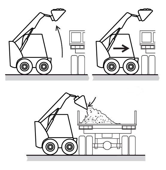
2.Drive slowly forward and stop with the bucket over the inside of the truck.
3.Tilt the bucket forward and dump the material into the truck bed.
4.When the truck is half-loaded, use the bucket to spread the load evenly.
5.Back away from the truck while tilting the bucket back and lowering the lift arm.
toward the truck.
•Dump with the wind behind you to keep dust away from your face, air filters and fans.
Backfilling Holes and Embankments
Do not drive too close to an excavation or ditch. Be sure the surrounding ground has adequate strength to support the weight of the machine and the load.
1.(Figure 74) Lower the bucket a few inches from the ground. Slowly drive forward until the front edge of the bucket extends halfway over the edge of the hole or embankment.
2.Tilt the bucket forward to dump the material.
3.Tilt back and raise the bucket. Inspect the hole/embankment for proper filling.
4.Continue to dump material as necessary for proper fill.
5.Back away from the embankment while tilting the bucket back and lowering the lift arm.
Tips When Loading Trucks
•(Figure 73) The truck and machine working direction should form an angle of 45°.
•Only raise a full bucket to the height needed for dumping when you are driving in a straight line
Scraping with a Bucket
Important: Always scrape in the forward direction.
1.(Figure 75) Lower the lift arm down against the chassis frame.
2.Tilt the bucket forward until the cutting edge is at a slight angle to the surface being scraped.
3.Travel slowly forward. Material can flow over the cutting edge and collect inside the bucket.
4.Tilt the bucket back and raise it to scoop up material.
Grading
Grading Without Float
1.(Figure 76) Raise the bucket slightly and tilt it forward.
2.Release material from the bucket while traveling forward.
3.Tilt the bucket forward and adjust the lift arm height until the cutting edge is slightly above the ground.
4.Drive in reverse, smoothing the material released in step 2 with the front edge of the bucket.
Check that the work area is clear of people and obstacles. Always look in the direction of travel.
Grading Using Float
Make sure the bucket is lowered to the ground before activating the lift arm float. Activating float with an attachment raised will cause it to fall to the ground, which can cause severe injury or death.
Do not drive the forward with the lift arm float activated. Damage to the machine and/or loss of control can result.
1.(Figure 77) Lower the bucket to the ground.
2.Activate the lift arm float. See “Lift Arm Float” on page63 for information about the float feature.
3.Tilt the bucket forward so it stands on the cutting edge at a 30°-45° degree angle to the surface being leveled.
4.Drive in reverse, dragging the floating bucket. Adjust the tilt angle of the bucket while driving in reverse to control the spread of the material.
Check that the work area is clear of people and obstacles. Always look in the direction of travel.
Using Pallet Forks
Safety Instructions When Working with Pallet Forks
Read the “Safety” section in this manual, starting on page9, before working with pallet forks. Pay special attention to the “During Operation” information, starting on page11.
Follow all instructions in the Operator's Manual provided with the pallet forks.
Always follow the information included in the “Safety” sections. Serious injury or death can occur if the safety information is not followed.
Always approach the load from a straight-ahead position. Position the fork arms underneath the pallet, as far as they will go, so the load is distributed as closely as possible to the fork frame. Position the fork arms as far apart as possible. Load both fork arms evenly.
Lift, transport and unload loads only on firm and level ground with sufficient load-bearing capacity.
Always transport the load close to the ground as is safely possible. Observe minimum ground clearance.
Use pallet forks for material handling and/or material transport only.
Never lift a load using only one fork arm.
Make sure the fork arms are safely locked onto the fork frame before use.
Do not lift unstable material, or material that is not properly secured on the fork arms.
Never leave a machine with the forks raised or a load unattended. Make sure all persons stay clear of suspended loads.
DO NOT exceed pallet fork load center and/or lifting capacity. See “Payloads/Capacities” on page116.
Do not use high travel speed range when using pallet forks.
DO NOT use standard fork arms as reverse (inverted) forks.
Never allow a load to get closer than 6 m (20 ft.) to overhead electrical lines.
DO NOT push, pull or shove the fork arms, or move them in at a slanting angle; the resulting lateral forces can damage the fork arms.
DO NOT pull loads off the fork arms, or allow loads to fall onto the forks arms.
DO NOT tilt the pallet forks to raise loads.
DO NOT lift or transport molten material with pallet forks.
Repair work on fork arms must be performed only by authorized personnel.
Always keep pallet fork arms clean.
Secure loads as directed in the pallet fork Operator's Manual to prevent the loads from falling.
Never modify pallet fork arms.
Do not lift or transport persons on the pallet forks.
Do not drive on public roads with pallet forks installed on the machine.
Do not stack loads which are not properly packaged or have damaged pallets/stacking containers. Do not stack loads on top of loads, which may have shifted.
Always tilt pallet forks back slightly during transport to help retain the load.
Do not use bent, cracked, or otherwise damaged fork arms/pallet forks.
Always inspect pallet forks each time before using. Refer to the pallet fork manufacturer’s documentation and/or contact the pallet fork manufacturer for information regarding safe pallet fork condition criteria:
•Check the fork arm locks for proper function and/or damage. Do not use pallet forks with damaged locks or locks that do not function properly.
•Visually check the fork arm hooks and/or bends for cracks and/or deformations. Do not use fork arms that are cracked and/or have deformations that make the fork arms unsafe.
•Do not use fork arms that have bends or blades that have more than 10% of the original material worn away.
•Check the fork arms blades and tips for deformations or holes.
Transporting Loads Using Pallet Forks
Important: When the self-leveling feature is on, the tilt angle of the attachment is kept constant, relative to the ground plane, when the lift arm is raised. When the lift arm is lowered however, self-leveling is not activated. Refer to “Self-Leveling (Option)” on page66 for more information about the selfleveling feature.
Loading Pallet Forks
1.Stop the machine immediately in front of the material.
2.Position the fork arms parallel to the ground.
3.Make sure the fork arms are adjusted as far apart as possible, as allowed by the load, and are both the same distance away from the center-line of the load.
4.Adjust the height of the fork arms to fit the lifting area at the bottom of the pallet.
5.Drive slowly and carefully forward until the fork frame contacts the material.
6.Make sure the pallet is evenly and safely positioned on the pallet fork arms.
Lifting Loads Using Pallet Forks
7.Apply the parking brake.
8.Slowly raise the pallet forks. Do not raise the pallet forks any higher than required. Make sure to not exceed pallet fork load center and/or lifting capacity.
9.Lower the load immediately if you are unsure of the load, the equipment, or in case of any unsafe circumstances.
10.Tilt the pallet fork frame back slightly, to help retain the load.
Transporting Load Using Pallet Forks
11.Make sure the area around and behind the machine is clear of bystanders and obstacles.
12.Slowly and carefully drive in reverse and lower the pallet forks to transport position (“Attachment Transport Position” on page63), when it is safe to do so.
13.Carry the load as low as safely possible during transport. Observe minimum ground clearance. Refer to “Attachment Transport Position” on page63.
14.Drive slowly and carefully forward straight toward the place where the load will be set down.
Setting Down Loads Using Pallet Forks
Note: If the load will be placed on top of stacked material, make sure to align the load in the center of the stack.
Do not stack loads which are not properly packaged or have damaged pallets/stacking containers. Do not stack loads, or on top of loads, which have shifted.
15.Raise the pallet forks slightly above where the load will be placed.
16.Tilt the pallet forks as needed to level the fork arms.
17.Carefully drive slowly forward until the load is positioned precisely above where the load will be placed. Use care when aligning the load with a stack.
18.Slowly and carefully lower the lift arm until the load is placed.
19.Make sure the fork arms are no longer bearing weight and are free to be retracted.
20.Make sure the area around and behind the machine is clear of bystanders and obstacles.
21.Slowly and carefully drive in reverse away from the placed load until the lift arm can be lowered to transport position. See “Attachment Transport Position” on page63.
22.Slightly tilt the pallet fork frame backwards.
Loading and Transporting the Machine on a Transport Vehicle
Warning
Park the transport vehicle on a level surface. Be sure the vehicle and its ramps have the weight and size capacity to support the machine Make sure the driver of the transport vehicle knows the overall height, width and weight of the vehicle, including the loaded machine, before starting transport. See “Weights” on page 116.
Make sure the load does not fall short of the minimum axle load of the steering axle, otherwise the transport vehicle’s steering could be seriously affected.
Make sure the transport surface and the loading ramps are clear of debris and slippery material that may reduce traction.
Secure the loading ramps to the transport vehicle before loading. Position the loading ramps at the shallowest possible angle. Do not exceed an angle of 15°. Only use ramps with anti-skid surfaces. Move the machine on and off the vehicle ramp slowly and carefully
Position the machine at the lowest possible position on the transport platform, with the center of gravity of the load over the centerline of the transport vehicle Distribute partial loads to ensure an even load across the axles of the transport vehicle.
Secure the machine properly so it cannot move during transport. Consider all possible transport conditions such as: heavy braking, evasive maneuvers, and uneven or rough roadways. Always use the proper tie-down points when using straps and chains. See “Machine Orientation” on page2.
Failure to follow these instructions could result in an overturn accident.
Important: Observe all local regulations governing the loading and transporting of equipment (Reference: U.S. Federal Motor Carrier Safety Regulations, Section 392). Ensure that the hauling vehicle meets all safety requirements before loading the machine.
1.Park the transport vehicle on a level surface. Block the front and rear tires on the transport vehicle.
2.Before starting, check the engine oil level. The oil level must be at the “Full” mark on the dipstick. Add oil if needed. See “Checking Engine Oil Level” on page87.
Important: When loading and driving on ramps, the engine can be damaged if the engine oil level is too low.
3.Start the machine and raise the hitch plate/attachment enough so that it will not touch the loading ramps.
4.Slowly and carefully drive in reverse up the ramp onto the transport vehicle.
Important: Do not adjust travel direction while traveling on the ramps. Instead, drive down off of the ramps, and re-align the machine with the ramps.
5.Position the machine at the lowest possible position on the transport platform, with the center of gravity of the load over centerline of the transport vehicle.
6.Lower the hitch plate/attachment to the transport platform, turn off the engine and remove the key.
7.Raise the operator restraint bar to lock out the hydraulic functions. If applicable, close the cab door and lock it. Do not allow anyone to stay in the cab.
8.Fasten the machine to the hauling vehicle at the points indicated by the tie-down decals (Figure 78).
9.Place blocks in front and behind wheels to prevent movement.
10.Measure the clearance height of the machine and transport vehicle. Post the clearance height in the cab of the transport vehicle.
Note: Before transporting the machine through heavy rain, close off the exhaust pipe with a cap or suitable adhesive tape.
50950503/E0521
Towing
Warning
Towing the machine is not recommended as a means of transportation.
Note: The machine may be equipped with an optional brake release. Refer to “Brake Release Operation (Option)” on page60 for more information.
Use the tie-down/retrieval point in situations where lifting the machine is not possible and the overall distance the machine must be moved is less than 100 feet (30.5 m). Retrieve/tow the machine at 6 mph (10 kph) or less.
Connect the towline to both tie-down/retrieval points at the front or the rear of the machine. Use of only a single retrieval point or connecting the towline to any point on the machine other than a designated tie-down/retrieval location could damage the machine.
Important: Towline capacity must be at least 1.5 times the gross weight of the machine. Towline length cannot allow the maximum towing angle to exceed 20°.
Note: Tow the machine for short distances only, such as towing it onto a trailer.
Lifting the Machine Using a Crane or Hoist
Note: Single-point and four-point lift kits are available for lifting the machine. Contact you dealer for more information.
Warning
Contact your dealer for available lift kits for the machine. Do not lift the machine without an approved lift kit installed.
Before lifting, check the lift kit for proper installation. Securely fasten the lifting gear to the machine at the designated lift points. When using any lift kit, follow the directions included with the lift kit.
Never allow riders in the operator’s compartment while the machine is lifted. Keep clear of suspended loads. Keep everyone a safe distance away from the machine while it is lifted.
The machine may only be crane-lifted with an empty bucket, empty pallet forks, or with no attachment. Never lift the machine with any other attachment installed. Never lift the machine with a load in the bucket or on the pallet forks.
Lift equipment used and its installation is the responsibility of the party conducting the lift. All rigging MUST comply with applicable regulations and guidelines.
1.If a bucket is attached, make sure it is emptied. If pallet forks are attached, remove any load from the pallet forks.
2.Raise the restraint bar to apply the parking brake and lock out the hydraulic functions.
3.Turn off the engine and remove the ignition key. Close the doors and the engine cover. Do not allow anyone to stay in the cab.
4.Using suitable lift equipment, hook into the lift kit lifting points. Adjust the length of the slings or chains so the machine is level when lifted.
Note: The machine may be slightly off level (10 degrees max.) when lifted.
5.Center the hoist over the ROPS/FOPS. To prevent shock loading of the equipment and excessive swinging, slowly lift the machine off the ground. Perform all movements slowly and gradually. As needed, use a tag line to help position the machine and keep it from swinging.
Diesel Particulate Filter (DPF) Regeneration Procedures (DPF Models)
The Diesel Particulate Filter (DPF) treats exhaust emissions in compliance with Tier 4/Stage 5 emission standards. The DPF filter relies on high exhaust temperatures. Periodic DPF maintenance (regeneration) is required, dependent upon machine operation load / temperature.
Note: Machines operated primarily at high loads and operating temperatures require less frequent DPF maintenance. Extended periods of engine idling rapidly increases DPF soot levels, requiring more frequent regeneration operations. There are 3 modes of DPF regeneration:
• Passive / Assist Regeneration: Occurs automatically without operator input. Passive/assist regeneration does not affect machine operation.
• Reset Regeneration: Occurs automatically, but can be inhibited by the operator. Increases exhaust gas temperatures. Reset regeneration occurs approximately every 100 hours of operation. See “Reset Regeneration” on page75.
Note: Reset regeneration effectiveness is improved if the machine is operated at mid- to high-throttle settings when reset regeneration mode is in progress.
• Stationary Regeneration: Requires operator action to initiate and takes approximately 25-30 minutes to complete. See “Stationary Regeneration” on page75.
Important: The machine cannot be operated and must be parked in a well-ventilated area away from flammable materials when stationary regeneration is in progress.
There is a possibility of carbon monoxide poisoning if stationary regeneration occurs in an enclosed space. Always perform stationary regeneration in a well-ventilated area.
Reset Regeneration Inhibit
During regeneration, there will be high exhaust gas temperatures, even at low load. Stay clear of the DPF during regeneration.
Reset Regeneration
Important: Reset regeneration can be prevented from occurring. See “Reset Regeneration Inhibit” on page75.
Reset regeneration occurs automatically (unless inhibited) approximately every 100 hours of operation.
Note: Reset regeneration effectiveness is improved if the machine is operated at mid- to highthrottle settings while regeneration is in progress.
When reset regeneration occurs, the DPF in-progress (elevated temperature) symbol (K, Figure 79) displays on the screen.
DPF regeneration inhibit prevents reset regeneration from occurring. Regeneration is not recommended, as this will eventually cause significant reduction in engine power and will force premature DPF soot filter replacement. To temporarily inhibit reset regeneration, hold down button (U, Figure 80) until the strikethrough in the Reset Regeneration symbol (W) turns to red.
Note: DPF inprogress (elevated temperature) symbol (K, Figure 79) will not be displayed when reset regeneration is inhibited.
Stationary Regeneration
Stationary regeneration may be periodically required to reduce DPF soot build-up. The frequency of stationary regeneration is dependent upon machine operation and engine load. The machine cannot be used during stationary regeneration and cannot be moved without interrupting the stationary regeneration process. When stationary regeneration needs to be performed, the regeneration request screen (Figure 81) displays on the information center electronic display.
Note: The stationary regeneration request screen can be temporarily dismissed by pressing the reset regeneration inhibit button (U, Figure 80) for 3 seconds. Until the previous screen displays. The stationary regeneration request screen will return 1 minute after being dismissed, for as long as the request remains active.
Important: Perform stationary regeneration as soon as possible when the stationary regeneration request screen displays. Postponing stationary regeneration for extended periods will cause significant reduction in engine power and will force premature DPF filter core replacement.
To proceed with stationary regeneration (Figure 82):
1.Park the machine in a safe, wellventilated location away from flammable materials.
2.The following conditions need to be met before stationary regeneration continues:
A.Press the button on the control keypad (page34) or lift the operator restraint bar to apply the parking brake. A checkmark is displayed next to the parking brake symbol (A).
B.When engine coolant has reached operating temperature (above 140° F / 60° C, a checkmark is displayed next to the coolant temperature symbol (B).
C.Place throttle controls to the lowest speed setting. A checkmark is displayed next to the engine RPM symbol when the engine is running at low idle.
3.When all three checkmarks (A, B & C) are displayed on the Stationary Regeneration screen, press and hold the button (Z) until the Stationary Regeneration In-Progress screen displays (Figure 83).
22 %
Note: Stationary regeneration can be interrupted at any time by releasing the parking brake, advancing the throttle, or stopping the engine. Stationary regeneration must start again from the beginning if it is interrupted.
Stationary regeneration completion percentage is displayed as during the stationary regeneration progresses. Progress percentage disappears when stationary regeneration completes.
Note: Stationary regeneration takes approximately 25-30 minutes.
It is not necessary to stay in the machine during stationary regeneration. Keep the machine under observation while regeneration is in progress in case of malfunction. Keep bystanders away from the machine while regeneration is in progress.
Forcing Stationary Regeneration
Stationary regeneration can be performed at any time after 50 operating hours following the previous stationary regeneration.
To perform stationary regeneration ondemand:
Press button (Y, Figure 84) associated with the DPF regeneration symbol (X), until the regeneration screen displays. Refer to “Stationary Regeneration” on page75 to proceed with stationary regeneration.
DPF Maintenance
DPF soot filter replacement is required when the DPF (Diesel Particulate Filter) Service Screen (Figure 85) displays.
Note: Contact your dealer when the DPF Service screen displays.
Camera Observation System
A camera observation system is optionally available on all models. The camera observation system utilizes a rear-facing camera mounted within the rear door of the machine to provide full visibility to the region behind the machine of which portions of that region may otherwise be masked by the machine’s structure.
The camera system is configured to turn on automatically when the machine’s ignition switch is moved to the “ON” position. The camera image is displayed on the monitor which is centered above the front door opening of the operator’s compartment.
The vertical viewing angle of the monitor is adjustable by loosening the knobs positioned on either side of the monitor. Prior to operating the machine the operator should check the monitor to verify that the monitor is positioned at the optimum viewing angle for them.
As an integral safety feature of the machine it is important for the operator to verify that the camera system is operating properly prior to moving the machine. A camera system that is operating properly will display a sharp image that is free of any obstructions when the key is switched on. The displayed image should be centered on the area directly behind the machine. If the displayed image does not meet this criteria the following system checks can be made:
•While the system is configured to power up automatically upon key on, depress the system power button at the display to see if the system powers up.
•Verify that the electrical connections to the monitor and camera are intact. This includes checking the A/V cable connection into the rear of the monitor and the camera connection to the camera extension cable located in the engine compartment in close proximity to the rear door hinges.
•Roll back the ROPS/FOPS and check the camera system harness connections forward of the engine flywheel housing. The connection of the camera system power harness to the accessory power connections in the chassis harness are located in this region. Verify that these connections are intact.
•Remove the right A-pillar cover within the ROPS/FOPS and locate the fuse holder in the camera system power harness located therein. Verify that the two Amp fuse within is intact and fully inserted into the fuse holder terminals.
•If the monitor displays a picture but that picture is not bright and clear, verify that the camera lens is clean and that the camera is properly aligned with the aperture in the rear door. The mounting brackets allow for left/right, up/down, and fore/aft adjustment. When making adjustments, ensure that the resulting pictures displayed on the monitor squarely shows the area behind the loader.
Additional troubleshooting measures are detailed in the camera observation system manual for instructions on how to correct any issues.
If the camera system is not able to be made functional after these initial checks, contact your dealer for service. A camera system that is unable to provide a clear image of the rear of the machine should be considered disabled and the machine should not be operated until the camera is made to function properly again.
Back-Up Alarm
A back-up alarm system is optionally available which serves to warn people working in the area around the machine of the machine’s rearward movement. The back-up alarm is installed within the engine compartment on the inside surface of the rear door. The alarm emits a tone whenever the machine begins to move in the rearward direction.