2 minute read
Table 7: Status, Maintenance and Error Code Screens


DM1 Screen
Displays engine, drive system, control, and safety system error code message information. Number of available messages is displayed at the top left of the screen (T). Use buttons (P and Q, Figure 20) to scroll through the messages. See “Engine Diagnostic Trouble Codes (DTC)” on page108 for specific error code details.
DM2 Screen
Continuation of error code message display along with DM1 Screen. Number of available messages is displayed at the top left of the screen (T). Use buttons (P and Q, Figure 20) to scroll through the messages. See “Engine Diagnostic Trouble Codes (DTC)” on page108 for specific error code details.
Input Status
Displays input information from electronic control modules, showing real-time machine component/control state. Status colors indicate the following:
• Green – Active
• Black – Inactive
Output Status
Displays output information from electronic control modules, showing real-time feedback state of machine components. Status colors indicate the following:
• Green – Active
• Black – Inactive.
• Yellow – Standby or Not Applicable
• Red – Short Circuit
Controls
Ignition Keyswitch
The Ignition keyswitch is located near the top of the right door pillar.
Ignition keyswitch positions are:
• OFF Position
: With the key turned fully counterclockwise, power from the electrical system is disconnected from the controls and instru- ments. This is the only position from which the key can be inserted or removed.
• ON/RUN Position: With the key turned one position clockwise from the OFF position, electrical power is supplied to all controls and instruments.
• START Position: With the key turned and held fully clockwise, the electric starter engages. Release the key to ON/RUN position when the engine starts.
Throttle Controls
On machines equipped with throttle knob (Q, Figure 22), engine speed is controlled with throttle knob and optional foot throttle (P, Figure 24), if installed.


Throttle knob (Q) is the primary throttle control. The throttle is set with the knob to the desired idle/run position.
On machines equipped with throttle lever (T, Figure 22), engine speed is controlled with throttle lever and optional foot throttle (P, Figure 24), if installed.
Throttle knob (T) is the primary throttle control. The throttle is set with the lever to the desired idle/ run position.

On machines equipped with optional throttle pedal (P, Figure 24), the pedal can be used to increase engine speed whenever additional power is required. When the optional pedal is released, the engine returns to the speed set by throttle knob (Q, Figure 22).
Travel Drive, Lift and Tilt Controls
The machine is equipped with one of three control systems:
•T-Bar Controls: see “T-Bar Controls” on page43.
•Joystick Controls: see “Joystick Controls” on page45.
•Hand and Foot Controls: see “Hand and Foot Controls” on page47.
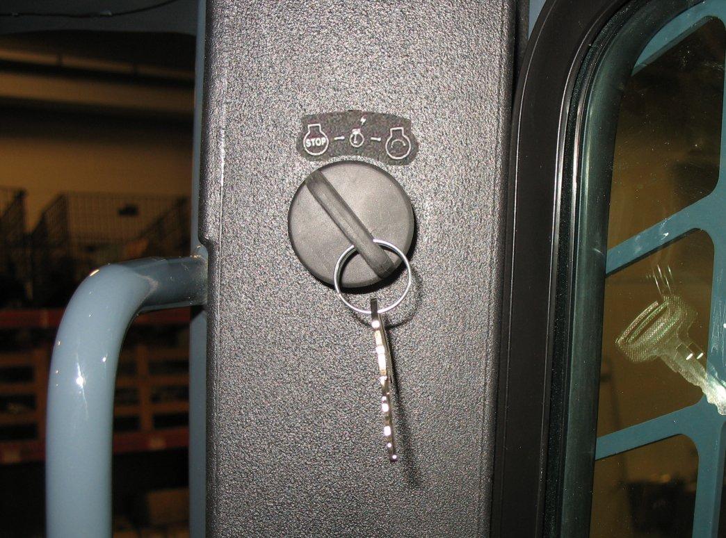
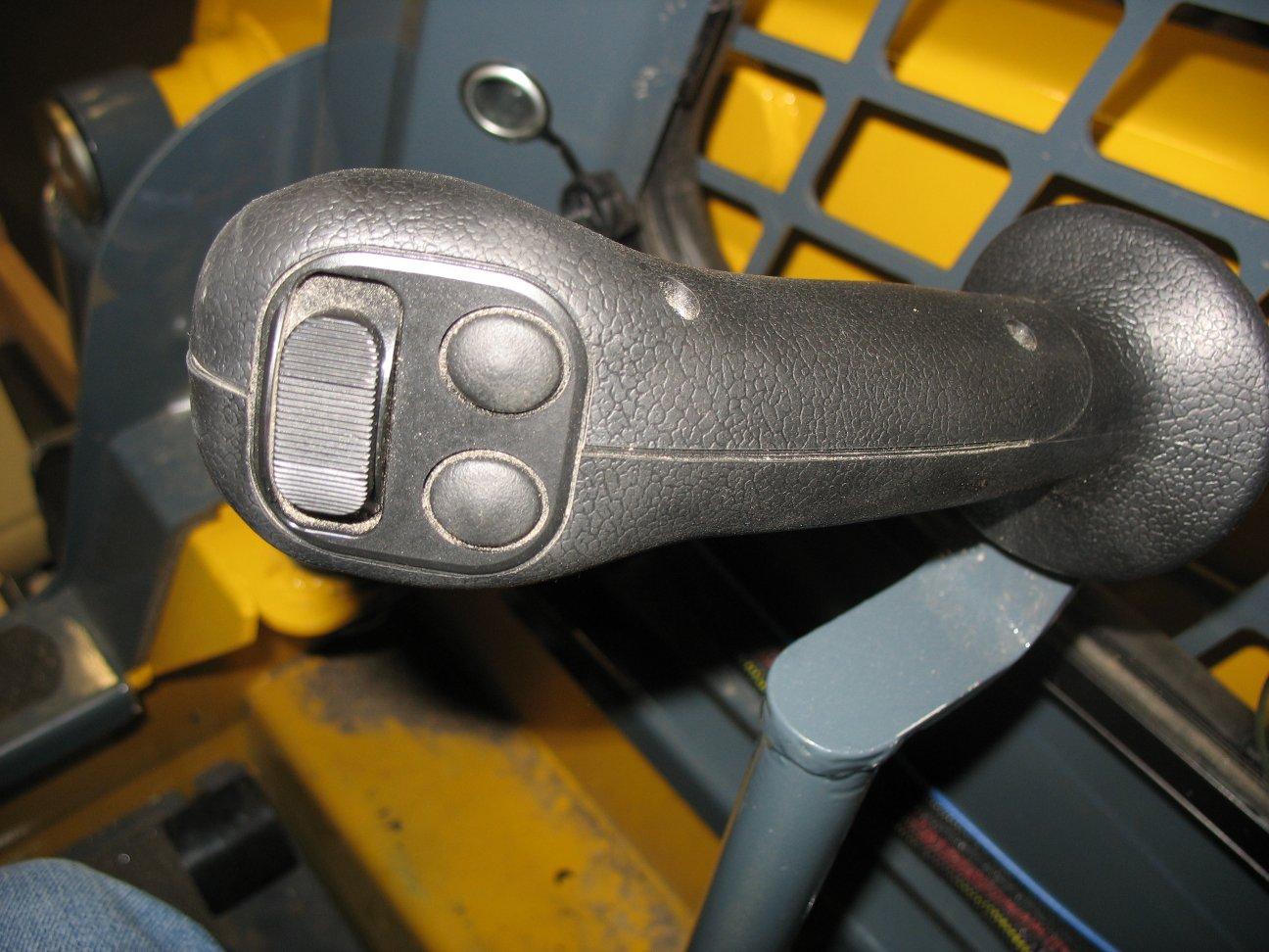
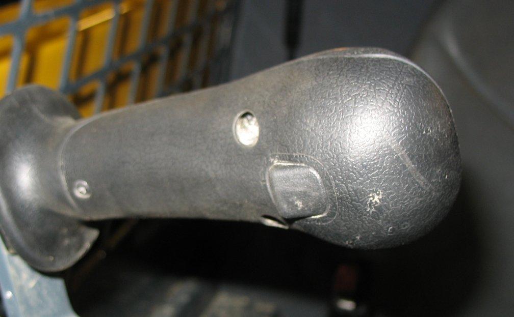
T-Bar Controls
On T-bar-equipped machines, the left T-bar controls the travel drive, and the right T-bar controls the attachment lift and tilt.

ALeft T-Bar Controls drive forward, reverse, turn, and speed. See “Drive Control (Left T-Bar)” on page44.
BRight T-Bar Controls lift arm raise/lower, float, and attachment tilt. See “Lift/Tilt Control (Right T-Bar)” on page44.
CTwo-Speed Selection Button
DHorn Button
Not Available.
Activates horn.
EHydraglide™ Button Activates Hydraglide™. See “Hydraglide™ Ride Control System (Option)” on page50. F INACTIVE Button is inactive on T-Bar Controls.