CHAPTER 14 SET-UP & ASSEMBLY CRATED UNIT The MC2175 Mower Conditioner is shipped from the factory in two separate shipping bundles: the Main Frame package and the Drawbar package. The Main Frame is packaged at the factory in such a way that the front of the Header is next to the floor and the Windrow–forming Chamber is towards the ceiling. Discardable shipping mounts (feet) are secured to the front of the Header for additional stability during warehousing. Depending on facilities, the unit can either be handled with a forklift truck (capable of carrying at least 3100 lb or 1410 kg) or, with a 2 ton overhead hoist, using lifting eyes provided. In either case, handle the machine carefully, so as NOT to damage it. If a forklift is going to be used, BE SURE to spread the forks as far apart as possible and insert them into the space between the Header and Trailer Frame Tube.
DANGER Do NOT allow anyone near the unit, while it is being lowered. Also, BE SURE that the chains are long enough and strong enough to do the job.
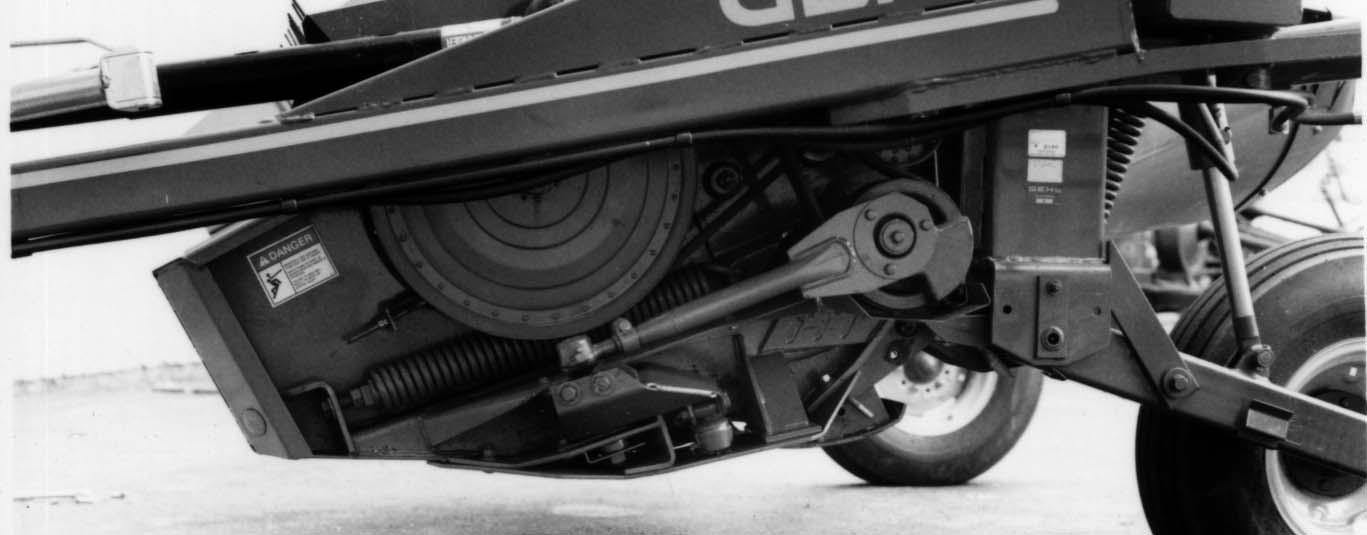
NOTE: A spreader bar, that is at least as wide as the distance between the Mower Conditioner legs, MUST be used, to keep the chain apart and prevent the chain from crushing the sides of the Windrow Forming Chamber. In addition, BE SURE that the chain is long enough so that the Forming Chamber will clear the spreader bar as it is being pivoted down. 4.
WARNING BEFORE attempting to lift the unit with a forklift, securely attach chains from the shipping mounts to the forklift, on both ends of the unit, to prevent the unit from swinging–away, when the unit is picked–up. BE SURE also that nobody is close to the unit, while unit is being transported in the shipping position.
NOTE: When pulling on the legs, the hydraulic Lift Cylinders may extend slightly.
ASSEMBLY Proceed to set up the Mower Conditioner using the following steps: 1.
UNCRATING UNIT (Fig. 53) After the machine is placed in its uncrating location, use the following steps and the drawing provided to properly uncrate it:
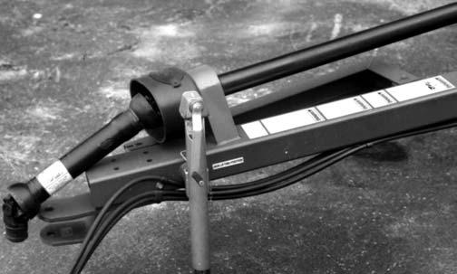
Install the Drawbar (Tongue), which was shipped separately, using the Pivot Pin to attach it to the Frame. Secure the Pivot Pin with the attaching hardware provided.
NOTE:
It may be necessary to raise and block the front of the Header, to obtain the correct alignment, for installing the Pivot Pin. 2.
Install and lock the Hitchjack, onto the Drawbar Hub, and raise the Drawbar until the shipping mounts are off the ground.
Mount the Wheels and Tires onto the Wheel Hubs and torque the Lugs to 90 ft–lb.
3.
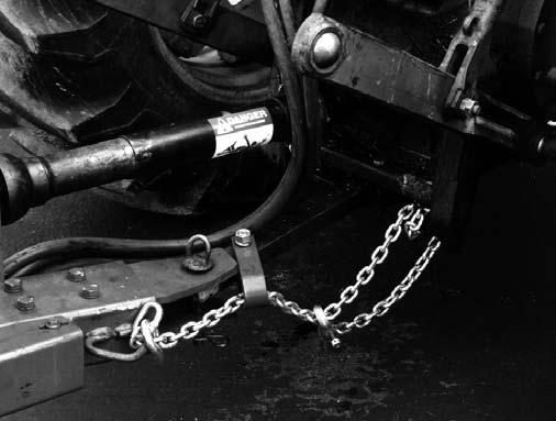
Wrap a long heavy chain around both legs of the unit, below the axles, and securely attach it with a spreader bar to the forklift carriage.
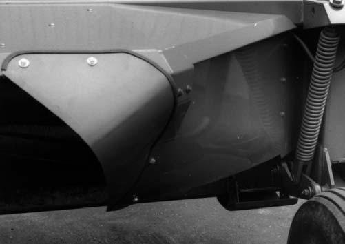
Remove the shipping mounts from both sides of the Header. Reposition the Pushbar in the top two holes of the Header End Panels.
4.
Remove the two shipping links that connect the Header to the Mower Conditioner Frame.
1.
Remove all items that are banded to the unit (Wheels, Tires, PTO, ...etc.).
2. 3.
52
Keeping tension on the chain at all times, raise the forklift carriage to a point approximately 2 feet higher than the end of the Windrow Forming Chamber, as shown in the drawing provided. Then, slowly pull and lift on the Mower Conditioner to rotate it around and rest it on the floor.