16 minute read
CHAPTER 9 SERVICE

General Information Caution
BEFORE proceeding to perform all Service routines on this unit, exercise the MANDATORY SAFETY SHUTDOWN PROCEDURE (page 8).
NOTE: The following information is also referred to in the Troubleshooting chapter of this manual. It should be understood that all services, detailed in this chapter, are Owner-Operator responsibilities. Where indicated, certain service routines should only be carried-out by (or under the direction of) an authorized GEHL equipment dealer.
SEALED BALL BEARING REPLACEMENT (Fig. 26)
Sealed Ball Bearings are used on various Shafts, around the unit. This type of Bearing is generally retained, in place, with a Self-locking Eccentric Collar. The Lock Collar has a counter bored recess, which is eccentric with the Collar bore. This eccentric recess engages or mates with an eccentric end of the Bearing inner ring, when the Bearing is assembled on the Shaft. The Bearing is engaged, on the inner ring cam, by the Collar. This assembly grips the Shaft tightly with a positive binding action that increases with use. The Collar Set Screw provides supplementary locking.
A Bearing can be removed from the Shaft by loosening the Set Screw and tapping on a punch which is placed in the drift pin hole, to loosen the Collar. Install Bearings with self-locking Collars in the following manner:
1.Place the Bearing and Collar on the Shaft with the cam surfaces next to each other. Tighten the bolts on the Bearing Retainers.
2.Mate the cam, of the Lock Collar, with the cam, of the Bearing inner ring.
3.Press the Locking Collar against the Bearing wide inner ring and turn it, in the direction of Shaft rotation until it tightly engages. Tighten the Collar further, by tapping on a punch inserted in the drift pin hole.
NOTE: Avoid damaging the Collar by overtightening it.
4.Last, tighten the Set Screw in the Locking Collar.
NOTE: Always tighten Lock Collars in direction that shaft is rotating.
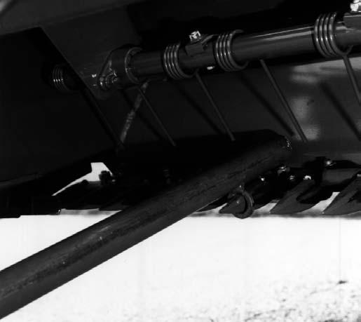
CUTTERBAR (Fig. 27) WARNING
BE CAREFUL when working around the Sickle. Wear heavy gloves to protect your hands and fingers. The majority of Mower Conditioner problems are caused by a lack of proper maintenance to the Cutterbar. The Cutterbar consists of two cutting surfaces, the Sickle Section and the ledger area of the Guard. For a clean, smooth cut, the Sickle Sections MUST operate very close to the ledger surface of the Guard.
NOTE: Regular washing of the Cutterbar area with water under pressure will improve performance and facilitate maintenance work.
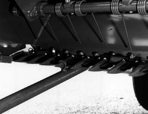
Sickle & Sickle Sections (Fig. 27 & 28)
For proper operation, The Sickle MUST be straight and without any twist. Also, the Sickle Sections should be firmly bolted to the Sickle strap. Worn or broken Sickle Sections should be replaced.
Warning
ALWAYS WEAR PROPER EYE PROTECTION, when working on Sickles and Sickle Sections. ALWAYS handle Sickles and Sickle Sections with caution to prevent injury or amputation.
NOTE: Top–serrated Sickle Sections are NOT designed for NOR intended to be sharpened. The top–serrated Sections, with serrations parallel to the Sickle strap, are sharpened by normal wear.
To remove the Sickle, remove the two bolts from the bottom Socket Bearing and pull out the Sickle. It will be difficult to remove the Sickle, if the Guards are badly bent or there is gum build–up on the Sickle. Straighten the Guards and wash off the Sickle with pressurized water, to aid in Sickle removal.
When installing a Sickle, torque the Socket Bearing bolts from 80 to 90 ft–lb (108 to 122 Nm).
NOTE: Check Sickle register after installing different Sickle, new Sickle head or new Socket Bearing.
Sickle Register (Fig. 28)
The Sickle is properly registered, when the center of the Section is positioned at the center of the Guard point, at each end of the stroke. Always check the Sickle register, at both ends of the stroke, and in the center of the Cutterbar. To adjust the Sickle register, use the following steps in the sequence given:
1.Position the Sickle in the center of its stroke (the edges of the Sickle Section should be aligned with the centerline of the Guard bolts).
2.Adjust the bottom Socket Bearing such that the inside edge of the Wobble Arm is parallel to the End Panel, when the Sickle is in the center of its stroke.
3.Adjust the top Socket Bearing such that the Sickle Section centerline is positioned at the centerline of the Guard point, at each end of the stroke.
4.Torque the bolts, in each Socket Bearing, from 80 to 90 ft–lb.
The Guard alignment is critical to insure a good shearing action, between the Sickle Sections and Guards, and to allow free movement of the Sickle through the Guards. When aligning or replacing Guards, BE SURE that:
1.The Guard tips are aligned.
2.The Guards are parallel to each other and to the Cutterbar (NOT cocked).
NOTE: Excessive Sickle drag can be caused by Sickle binding, due to the Guard tips NOT being aligned or the Guard being cocked. This drag can cause Sickle breakage, increased load on Bearings and Drive components and, excessive vibration.
Guard Alignment (Figs. 29 & 30)
Warning
BEFORE proceeding to work on Cutterbar, raise the Header, engage the Transport Locks (on both sides), install additional blocks, under both sides of the raised Header and exercise the MANDATORY SAFETY SHUTDOWN PROCEDURE (page 8).
When tightening Guard bolts, make sure that the Guards are parallel with the Cutterbar and each other. Tighten the Guard bolt on your right side first, while pushing the Guard rearward.
The Guard points can be aligned using the Roll Reversing & Guard Straightening Tool supplied. The Tool can be used to either bend the Guard points up or down. The Tool is stored in the Frame Channel with access gained by opening the right End Shield.
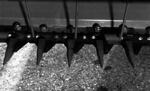
Hold–down Clips (See Fig. 28)
The Hold–down Clips keep the Sickle Sections down on the Guards, for a clean shearing action. The Hold–down Clips should be set with a maximum gap of 1/32”, between the Sickle Sections and the Hold–down Clips, with the Sickle Sections down on the Guards. The Hold–down Clips should NOT be so tight as to restrict free movement of the Sickle.
The Hold–down Clips are made of stamped steel and can be adjusted downward, by striking the top with a lead–headed hammer. Do NOT adjust a Hold–down Clip with a Sickle Section under it. Oil the Hold–down Clips, after they have been adjusted.

NOTE: BE SURE to align the Guard points, before adjusting any Hold–down Clips.
Sickle Drive
Socket Bearing Replacement (See Fig. 31)
When the top or bottom Socket Bearing is replaced, it will be necessary to check the Sickle register. The two Socket Bearing retaining bolts should be torqued from 80 to 90 ft–lb.
NOTE: BE SURE the Socket Bearing Clamps lineup with the slots of the piece they are clamping.
Wobble Arm Pivot Bearing Replacement (Fig. 31)
Loose or worn out Wobble Arm Pivot Bearings can cause noise and excessive vibration. A loose Bearing should be tightened and worn out Bearing replaced, before they cause damage to the other Sickle Drive components. Check Pivot Bearing tightness, before replacing the Bearings. The nut on the Pivot Pin should be torqued to 100 ft–lb, for proper Bearing tightness.
To replace the Wobble Arm Bearings, it is necessary to remove the Wobble Arm. After the Wobble Arm has been removed, replace the Bearings and races, as required. BE SURE to pack the Bearings, with grease, before reassembling.
Wobble Arm Replacement (Figs. 31 & 32 & see Fig. 28)
To remove the Wobble Arm, use the following steps:
1.Remove the left Rock Guard.
2.Remove the Socket Bearing retaining bolts from both the top and bottom Socket Bearings.
3.Remove the Pivot Pin Nut and Pivot Pin.
4.Remove the Wobble Arm.
To install a new Wobble Arm, use the following steps: NOTE: To reinstall the original Wobble Arm, use steps 6, 10 & 12.
5.Remove and save all Wobble Arm Pivot Shims, located above and below the Wobble Arm.
6.After packing the Pivot Bearing with grease, install the Wobble Arm and Bearing into the proper position and insert the Pivot Pin; BE SURE there is one Washer (PN 360–14855) backing both the top and bottom tapered Roller Bearings.
7.Hand–tighten the Pivot Pin Nut.
8.Install and hand–tighten the retaining bolts in the bottom Socket Bearing.
9.Use the Wobble Arm Pivot Shims to raise and lower the Wobble Arm, such that the Sickle Sections run from 0 to 1/32 (0.030)” above the first Guard, on the left end. Add as many Shims as possible, above and below the Wobble Arm, to fill the gap.
10.Torque the Pivot Pin Nut to 130 ft–lb, to seat the Bearing races. Then, back the Nut off. Re–torque the Nut to 100 ft–lb and install the cotter pin to lock the Nut.
11.Use the Socket Bearing Shims to position the Sickle strap in the Sickle strap opening of the left Guard such that: a.The Sickle strap touches the back of the Sickle strap opening, in the center of the stroke, and, b.The Sickle strap touches the front of the Sickle strap opening, at the ends of the stroke. Use only enough Shims to fill the opening.
12.Adjust the Sickle register, as described under the Cutter bar topic.
13.Tack–weld the Socket Bearing Shims to the Wobble Arm so they will NOT fall out, when the Sickle is removed.
NOTE: If the Wobble Arm Pivot Bushings in the Header Frame shows signs of wear, contact your Gehl Dealer for Bushing replacement information.
Pitman Bearing Replacement (Fig.
33 & see Fig. 27)
To remove the Pitman Bearing on the Pitman Pulley, use the following steps:
1.Remove the Screws and hardware and pull the Bearing Retainer and Pitman Arm away from the Bearing Assembly.
2.Remove the Bearing Assembly Retainer Bolt and Washers.
3.Remove the Eccentric Lock Collar (rotate counterclockwise) and remove the Bearing Assembly.
To install the new Bearing, use the following steps:
4.Place the Bearing Assembly on the Pitman Pulley.
5.Install and lock the Bearing onto the Pitman Pulley, by rotating the Lock Collar clockwise. Make sure that the Bearing Assembly is parallel to the surface of the Pitman Pulley and the end of the Lock Collar is flush with the end of the Stub Shaft.
6.Replace the Bearing Retainer Bolt and Washers.
7.Install Pitman Arm with Tube angled away from Frame and Bearing Retainer to Bearing Assembly making sure that Bearing Housing is positioned per Figure 33 (flat side toward Wobble Arm).
8.Install retaining hardware and torque to 30 ft lb (41 Nm).
Pitman Arm Replacement
To replace the Pitman Arm, follow the steps listed under the Pitman Bearing Replacement topic, with the exception of removing and installing the Bearing. After completing the Arm replacement procedure, check the Sickle register, as described under the Cutterbar topic.
Conditioner Rolls
Conditioner Roll Timing (Figs. 34, 35 & 36)
The Conditioner Rolls are properly timed when the lug of one Roll is centered in the groove of the mating Roll. BE SURE the Roll Drive Chain is properly tensioned, before adjusting or checking the Roll timing.
To time the Conditioner Rolls, loosen the bolts on the Timing Sprocket. The Timing Sprocket can have either a 9 or 12 bolt pattern. Go behind the Conditioner Rolls and center the lug of one Roll in the groove of the mating Roll. Torque the screws on the Timing Sprocket to half–torque (15 ft–lb) using a cross–point star sequence pattern (see Figure 35). Finish torquing bolts to full torque setting (30 ft–lb) using the above star pattern. Again, check the timing as the Rolls are rotated by hand.
NOTE: At NO time, should the lugs of the Conditioner Rolls touch each other during operation, as damage to the Conditioner Rolls, Bearings and Frame will result.
NOTE: When Conditioner Rolls are realigned, the top Roll Chain Drive alignment and Roll timing MUST be checked.

Roll Alignment (Fig. 34)
The Upper Conditioner Roll is properly positioned in the Frame when the Sprocket on the top Roll Shaft is locked in place. The position of the top Roll is non–adjustable. The lower Roll is to be centered in the Header Frame (NOT aligned with the ends of the top Roll). Move the lower Roll left or right by loosening the Bearing Lock Collars and shifting the Roll until centered in the Frame. MAKE SURE to lock Bearing Lock Collars after Roll is properly positioned.
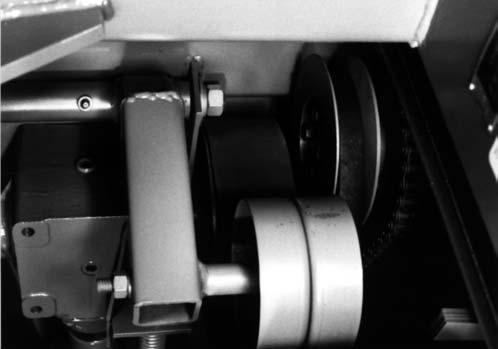
Conditioner Roll Drive Chain Tension (Fig. 34)
The Conditioner Roll Drive Chain tension is maintained by a spring loaded Idler. The Spring should be set to a compressed height of 1–3/4″ (44mm).
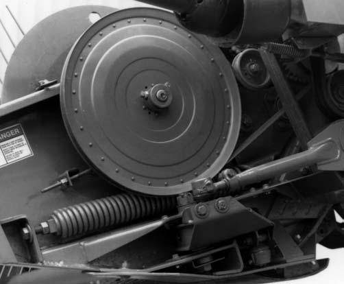
BANDED V–BELT (MAIN DRIVE BELT) (Figs. 37 & 38)
The Banded V–Belt on the Mower Conditioner is used to drive the Conditioner Rolls and Sickle. It is also an overload protection for the Conditioner Rolls and Sickle.
Banded V–Belt Tension (Figs. 37 & 38)
The Compression Spring, on the Banded V–Belt Idler, should be set at a 4–1/4” (108mm) overall length. The Spring–loaded Idler has been designed to protect the Driveline; overtightening the Idler will decrease this protection. The Spring should NEVER be tightened to less than 3–3/4” (95mm).
6.Install the two retaining bolts, for the Pitman Arm Socket Bearing, and torque from 80 to 90 ft–lb.
Banded V–Belt Alignment & Location (Figs. 37 & 38)
The Banded V–Belt should be aligned and located in the following manner:
1.The two Banded V–Belt Sheaves should be aligned with each other within 0.030″ (.76mm).
2.The two Shafts, which the Banded V–Belt Sheaves are mounted to, should be parallel to each other within 0.015″ (.38mm), over a span of 4″ (102mm).
3.The Banded V–Belt should be located such that the centerline of the inside groove is located 5–15/16″ (151mm) out from the End Panel.
Banded V–Belt Idler (Figs. 37 & 38)
The Banded V–Belt should be parallel to the two Banded V–Belt Sheaves, to place equal tension on each Band. The Idler position can be adjusted by loosening the Idler Pivot Bolt and making required readjustment.
DRIVE SHEAVE (Fig. 38)
The Drive Sheave, on the Output Shaft of the Gearbox, can be removed in the following manner:
1.Loosen and remove the cap screw.
2.Insert cap screws in the tapped Removal Holes of the Bushing Head.
3.Tighten the inserted screws, until the Pulley is loose on the Shaft.
Banded V–Belt Replacement (Figs. 37 & 38)
To remove the Banded V–Belt, use the following steps:
1.Remove the two retaining bolts from the top Socket Bearing.
2.Remove the Gearbox, following instructions under the Gearbox topic in this chapter. Then, remove the Banded V–Belt.
To install a new Banded V–Belt:
3.Slip the new Banded V–Belt over the Pitman Arm and onto the Pitman Pulley.
4.Place the Banded V–Belt over the Drive Sheave, on the Gearbox Output Shaft.
5.Replace the Gearbox, following details under the Gearbox topic in this chapter.
4.Remove the Pulley from the Shaft.
To replace the Pulley or install a new one, proceed as follows:
5.Make sure the tapered cone surfaces of the Bushing and the inside of the Pulley hub are clean.
6.Place the Bushing in the Pulley.
7.Place cap screws and lock washers loosely into the pull–up holes. Bushing remains fully expanded to assure sliding fit on Shaft.
8.With Key on Shaft, slide Pulley to the desired position on the Shaft.
9.Align the Pulley. Tighten the screws alternately and progressively, until all are torqued to 15 ft–lb. Do NOT allow the Pulley to be drawn into contact with the flange of the Bushing; there should be a gap of 1/8 to 1/4″ (3 to 6mm).
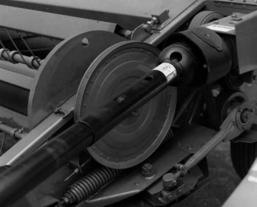
PITMAN PULLEY REMOVAL (Figs. 38 & 39)
To remove the Pitman Pulley from the lower Conditioner Roll Shaft, use the following steps:
1.Straighten tabs on Bolt Lock Ring. Then, loosen the six locking bolts on the inside of the Pitman Pulley. Loosen the bolts in two stages, using the sequence illustrated.
2.The Pulley should now be free to slide on the Shaft. It may be necessary to rap the Pulley to loosen the locking element.
PITMAN PULLEY INSTALLATION (Figs. 38 & 39)
To replace the Pitman Pulley or install a new one onto the Conditioner Roll Shaft, proceed as follows:
3.If the Pulley was just moved on the Shaft, skip to step 10.
4.Clean and oil (with common engine oil) the components shown in the drawing. Do NOT use grease.
5.Slide all of the components shown onto the lower Roll Shaft. The slits, in the individual locking elements, should be 180 degrees apart, in each set. The contact angles, between the individual locking elements, should be the same for both sets as shown.
6.Slide the Pitman Pulley over the components, on the Shaft, without rotating the Pulley.
7.Hand–tighten the six locking bolts, until all slack is removed between the various components.
8.Slide the Pulley in or out to line–up with the Banded V–Belt Drive Sheave (see Banded V–Belt Alignment & Location topic).
9.Torque the locking bolts to 15 ft–lb, using the sequence shown.
10.Now, torque the locking bolts to 30 ft–lb, using the sequence shown.
11.Bend up the tabs of the Bolt Lock Ring, to lock the Bolt positions.
NOTE: BE SURE the flange does NOT touch the Pitman Pulley, after tightening the locking bolts.
5.The Gearbox will now drop down, when the four Gear box bolts are removed. There are Shims, located between the Gearbox and the Gearbox Mount; note the position and quantity, for future reassembly.
NOTE: Internal component repairs and replacements should only be attempted by (or under the direction of) an authorized GEHL equipment dealer.
Replacement on Mower Conditioner
To replace the Gearbox onto the Mower Conditioner, use the following steps:

GEARBOX (Figs. 39, 40 & see
Removal from Mower Conditioner
To remove the Gearbox, use the following steps:
1.Remove the rear PTO assembly from the Gearbox Input Shaft.
2.Disconnect the Banded V–Belt Idler Tension Rod from the Idler.
3.Remove the Reel Drive Chain Idler.
4.Remove the three mounting bolts from the Bearing, on the end of the Gearbox Output Shaft.
6.Position the Banded V–Belt over the Drive Sheave, on the Gearbox Output Shaft.
7.Start the four Gearbox bolts into the Gearbox Housing.
8.Insert the Gearbox Shims into their original location. The Gearbox Output Shaft should be parallel to the lower Conditioner Roll Shaft, within 0.015” (.38mm), over a span of 4” (102mm).
9.Tightly secure the four Gearbox bolts.
10.Install the bolts for the Outboard Bearing onto the Output Shaft of the Gearbox. Do NOT force these bolts and thus place side load on the Gearbox Shaft which could result in early Shaft failure. If the bolts, for the Outboard Bearing, do NOT line–up, use the Shims, between the Gearbox and Gearbox Mount, to obtain the proper Output Shaft position.
11.Install the Reel Drive Chain and Idler, making sure that the Chain is properly aligned.
12.Reassemble the other loose items to complete the replacement procedure.
Reel Drive
Drive Chain Tension (Fig. 40)
The Reel Drive Chain tension can be adjusted by loosening the Pivot Bolt, in the Reel Drive Chain Idler, and raising or lowering the Idler, as required. The Chain should have 1/4” of total slack movement, in the bottom strand.
Drive Belt Tension (Figs. 40, 41 & see Fig. 38)
The Reel Drive Belt tension can be adjusted using the Threaded Rod. The Spring should be extended to an overall length of 8–3/4” (222mm).
NOTE: The Reel Drive Belt Spring–loaded Idler has been designed to protect the Reel. Overtightening the Idler will decrease this protection.
Drive Belt Replacement (Fig. 42)
To replace the Reel Drive Belt, it is necessary to disassemble the Variable Speed Drive Sheave following procedures outlined under the Reel Speed topic in the Adjustments chapter. BE SURE to adjust the Reel Belt tension, after installing a new Belt.
1 – Variable Speed Drive Sheave
2 – Banded V–Belt Idler
Fig. 42
HYDRAULIC LIFT CYLINDERS (Fig. 43)
The Mower Conditioner Lift System consists of a ”master–slave” cylinder arrangement, as shown. With a ”master–slave” setup, the hydraulic oil, from the rod end of the master cylinder, goes into the base end of the slave cylinder. Because of this arrangement, both cylinders will extend equally, under any load.
With a ”master–slave” arrangement, the cylinders can become un–phased such that the machine will raise unevenly (left end higher or lower than the right end). Use the following steps to re–phase the lift cylinders:
1.Completely raise and lower the unit several times, keeping the tractor hydraulic lever engaged, until NO cylinder movement is observed.
NOTE: The cylinders will move very slowly, while equalizing.
2.If the unit is still unequal, proceed to step 3 or 4, depending on the problem.
Warning
BE SURE there is NO pressure in the lines, when loosening the fittings. Hydraulic fluid, under pressure, can penetrate the skin. If injured by escaping fluid, see a doctor at once. Injected fluid MUST BE surgically removed by a doctor familiar with this type of injury or gangrene may result.
point as shown). With the fitting loose, raise the unit, until oil appears at the fitting. Then, retighten the fitting and repeat step 1.
4.If the master cylinder (left) will NOT raise fully, when the slave cylinder (right) is fully raised, loosen the fitting that goes into the slave cylinder (bleed point as shown). With the fitting loose, remove approximately 1/2 cup (4 oz) of oil for every one inch of cylinder length difference. Then, retighten the fitting and repeat step 1.
If the hydraulic cylinders become un–phased frequently, during use, it will be necessary to replace the piston seals in the master cylinder. Only replace the slave piston seal if it is leaking externally.
NOTE: A leaky tractor valve may cause one or both hydraulic cylinders to raise slowly, while cutting.
Telescoping Drives
NOTE: For safety reasons, service on the Telescoping PTO Drives should ONLY be performed by (or under the direction of) an authorized GEHL equipment dealer.
Over time, the Telescoping Drive Universal Joints may become worn and noisy and require service. As necessary, remove the Drive(s) from the Mower Conditioner and take them to your dealer.
TIRES & WHEELS
3.If the slave cylinder (right) will NOT raise fully, when the master cylinder (left) is fully raised, loosen the fitting into the slave cylinder (bleed
The Tires should be inflated to different pressures; 36 PSIG (252 kPa) on the right side and, 18 PSIG (126 kPa) on the left side. The Wheel lug nuts should be torqued to 90 ft–lb. The Wheel Bearings should be torqued to 55 ft–lb while rotating the Wheel back and forth at least 90 degrees, then, the slotted nuts should be backed off between 1 and 2 cotter pin slots.
Caution
Our Company does NOT sell replacement Tires. In addition, Tire mounting, repair and replacements should ONLY be attempted by a qualified tire manufacturer’s representative or by properly trained personnel following the tire manufacturer’s instruction. If you do NOT have such instructions, contact your tire dealer or our Company.
Warning
Inflating or servicing tires can be dangerous. Whenever possible, trained personnel should be called to service and/or mount tires. In addition, do NOT place your fingers on the tire bead or rim during inflation; serious injury or amputation could result. In any event, to avoid possible death or serious injury, follow the safety precautions below:
• BE SURE the Rim is clean and free of rust.
• Lubricate both the tire beads and rim flanges with a soap solution. Do NOT use oil or grease.
• Use a clip-on tire chuck with a remote hose and gauge which allows you to stand clear of the tire while inflating it.
• NEVER inflate beyond 35 PSI (240 kPa) to seat the beads. If the beads have NOT seated by the time the pressure reaches 35 PSI, deflate the assembly, reposition the tire on the rim, relubricate both parts and re-inflate it. Inflation pressure beyond 35 PSI with unseated beads may break the bead or rim with explosive force sufficient to cause death or serious injury.
• After seating the beads, adjust the inflation pressure to the recommended operating pressure listed.
• Do NOT weld, braze, or otherwise attempt to repair and use a damaged rim.