19 minute read
SAFETY


ALWAYS follow state and local regulations regarding use of a safety chain and transport lighting when towing farm equipment on public highways! A safety chain should always be used to retain the connection between the towing and towed machines, in the event of separation of the primary attaching system! BE SURE to check with local law enforcement agencies for your own particular regulations. Unless otherwise prohibited, use a Slow Moving Vehicle Emblem. Only a Safety Chain (NOT an elastic or nylon/plastic tow strap) should be used to retain the connection between the towing and towed machines, in the event of separation of the primary attaching system. Refer to Optional Features & Accessories chapter for Safety Chain.
Always use adequate lights or safety warnings when transporting machine on public roads and after dark. Check with the local law enforcement agencies for specific requirements. Refer to Optional Features & Accessories chapter for Transport Lighting Kit. To ensure continued safe operation, replace damaged or worn–out parts with genuine GEHL service parts, BEFORE attempting to operate this equipment.
Our Company does NOT sell replacement tires. In addition, tire mounting, service or inflation can be dangerous. Whenever possible, trained personnel should be called to service and/or mount tires, following the tire manufacturer’s instruction. If you do NOT have such instructions, contact your tire dealer or our Company. In any event, to avoid possible fatal or serious injury, follow the specific directive given in the Service chapter of this manual.
DO NOT get near the unit until the Reel and Conditioner Rolls have stopped rotating! Both mechanisms and the Sickle can continue to operate after the PTO is disengaged!
DO NOT attempt to hand feed or kick any crop or material into this machine!
REMEMBER, it is the owner’s responsibility for communicating information on the safe use and proper maintenance of this machine.
Always lower Header to ground when parking. Limit towing speed to 20 mph.


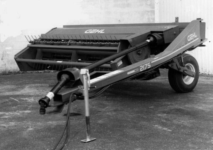
CHAPTER 5 CONTROLS & SAFETY EQUIPMENT
The Mower Conditioner is provided with several features for operator safety and convenience.
Caution
Become familiar with and know how to use ALL Safety Devices and Controls on the Mower Conditioner, BEFORE attempting to operate this equipment. Know how to STOP Mower Conditioner operation BEFORE starting it.
Drawbar Hitch Positioning Caution
A Drawbar Hitch Positioning device MUST ALWAYS be securely installed between the Drawbar and Mower Conditioner Frame, BEFORE attempting to move the unit.
Repositioning the Mower Conditioner Drawbar (Tongue), between the ”Transport” and operating positions, can be accomplished in either of two ways; hydraulically or mechanically.
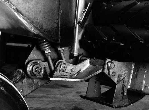
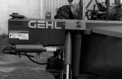
Hydraulic Hitch Positioner (Fig. 1)
A Hydraulic Hitch Positioner is available for remotely (from the tractor seat) relocating the Drawbar from the ”Transport” to the field operation positions. The Hydraulic Hitch Positioner package contains a double–acting hydraulic Cylinder, Hoses and a Transport Lock.
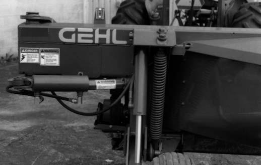
Caution
BEFORE transporting the Mower Conditioner on a public highway, BE SURE to install and lock the Positioner Cylinder, in the extended ”Transport” position, with the Transport Lock provided.
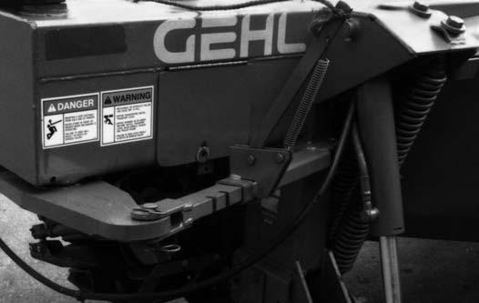
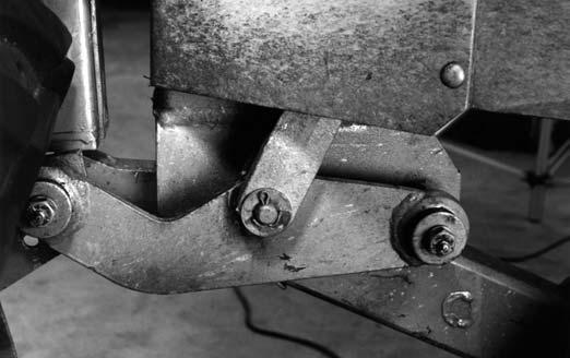
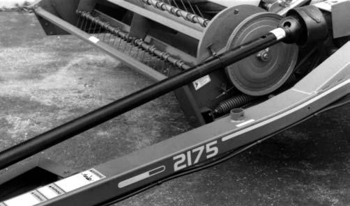
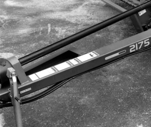
Mechanical Hitch Positioner (Fig. 2)
A Mechanical Positioner is available for remotely (from the tractor seat) relocating the Drawbar from the ’’Transport’’ to the field operation positions. The Mechanical Positioner package contains a Control Mechanism and a Control Rope.
Caution
BEFORE transporting the Mower Conditioner on a public highway, BE SURE to securely lock the Drawbar in the ”Transport” position.
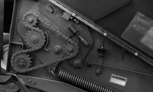
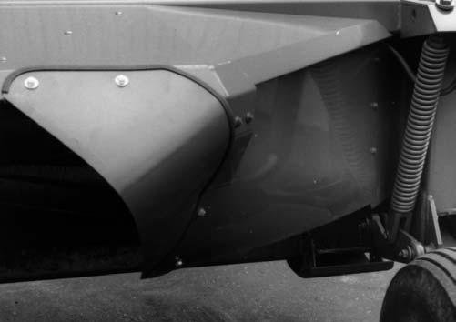
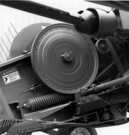
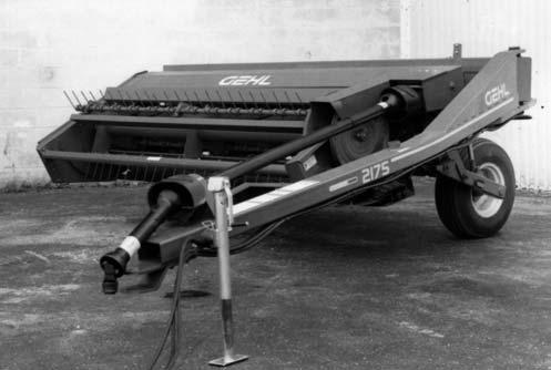
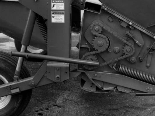
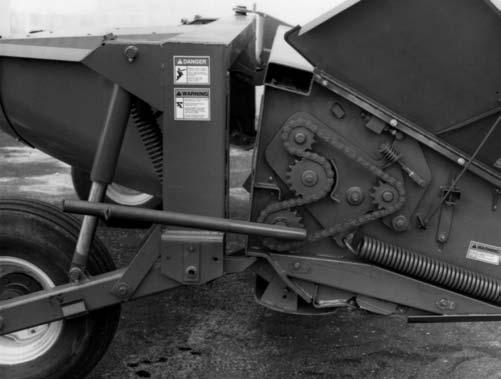
GUARDS & SHIELDS (Figs. 3 & 4)
Whenever and wherever possible and without affecting machine operation, Guards and Shields have been used, on this equipment, to protect potentially hazardous areas. In many places, Decals are also provided to warn of potential dangers as well as to display special operating procedures.
Warning
Read and observe ALL Warnings on the unit, BEFORE operating it. Do NOT attempt to operate this equipment unless ALL factory installed Guards and Shields are properly secured in place.
Implement Drive Line Shields
The Front Telescoping PTO Drive, between the PTO Tower and tractor PTO shaft, and the Rear Telescoping PTO Drive, between the PTO Tower and Gearbox, are equipped with rotating Shields.

Warning
BE SURE that the Rotating Shields on the Telescoping Drives turn freely BEFORE starting the tractor engine.
Miscellaneous Guards
Various latched and hinged Guards, Shields and Covers are provided on the Mower Conditioner to enable access for lubrication, service and adjustment.
Caution
BEFORE proceeding to perform any work on the Mower Conditioner and, BEFORE removing any Guards and opening any Covers and Shields, BE SURE to exercise the MANDATORY SAFETY SHUTDOWN PROCEDURE (page 8). BE SURE also to replace ALL Guards, Shields and Covers BEFORE operating the unit.
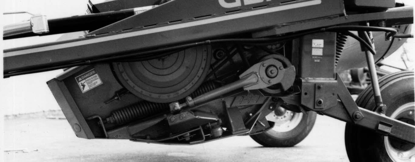
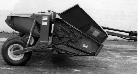
HEADER LIFT SYSTEM (Fig. 5)
The Mower Conditioner uses a remotely controlled (from the tractor seat) single–acting hydraulic Cylinder ’’master–slave’’ system, to raise and lower the Header.
Before transporting the unit, BE SURE to raise the unit as high as possible and activate the Transport Lock on both sides of the unit.
Caution
BEFORE transporting the Mower Conditioner, raise the unit as high as possible and engage both Transport Locks.
ROLL REVERSING & GUARD STRAIGHTENING TOOL (Fig. 6)
The Mower Conditioner is furnished with a special Tool for reversing the Conditioning Rolls to clear plug and, for straightening bent Sickle Guards, when required. When NOT in use, the Roll Reversing & Guard Straightening Tool is stored inside the Frame Tube. Access to the Tool is gained by locking open the large Right End Shield.
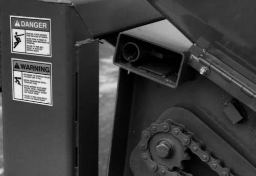
HITCHJACK (See Fig. 3)
A Hitchjack is furnished with the Mower Conditioner to support the machine when the tractor is disconnected as well as to facilitate aligning the Hitch Clevis with the tractor drawbar for hookup. When the Jack is NOT being used to support the Mower Conditioner, it can be removed and relocated to a ”storage” position on top of the Drawbar.

Warning
BE SURE the Locking Pin is properly seated into the holes through the Jack Tube and the ”Supporting Position” Hub on the Drawbar, BEFORE disconnecting the Mower Conditioner from the tractor.
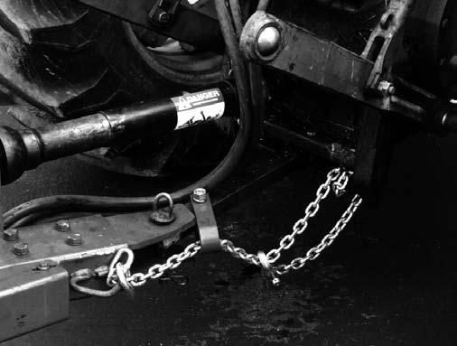
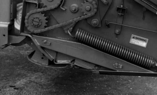
SAFETY CHAIN (Fig. 7)
Caution
ALWAYS follow state and local regulations, regarding a safety chain and transport lighting, when towing farm equipment on public highways! A safety chain (NOT an elastic or nylon/plastic tow strap) should always be used to retain the connection between the towing and towed machine, in the event of separation of the primary attaching system. BE SURE to check with local law enforcement agencies for your own particular regulations. NEVER transport the Mower Conditioner at speeds greater than 20 mph. Unless otherwise prohibited, use a Slow–moving Vehicle Emblem.
As required or when desired, the Mower Conditioner should be equipped with a safety chain and transport lighting for transporting the unit on public highways. A sturdy Chain Loop is welded to the side of the Drawbar to facilitate anchoring the chain. Refer to the Optional Features & Accessories chapter for ordering information.

Warning
BE SURE that the Telescoping PTO Coupler is properly secured to the tractor PTO shaft, BEFORE starting the tractor engine.
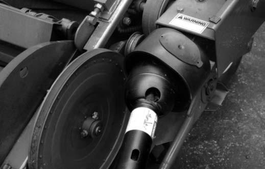
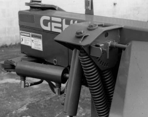
TELESCOPING DRIVE COUPLER (Fig. 8)
The Front Telescoping Drive is equipped with a Spring–loaded Locking Device to positively lock it onto the tractor PTO shaft. Depress the Locking Device against the Spring tension and slide the Yoke onto the tractor PTO shaft. Release the Locking Device and move the Yoke ahead or back until the Lock engages into the groove of the PTO shaft.

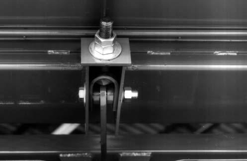
TRANSPORT LOCKS (See Figs. 1 & 5)
When the Mower Conditioner is going to be transported on a public highway, BE SURE to raise the unit all the way up and engage both Lift system Transport Locks. For units with a Hydraulic Hitch Positioner, BE SURE also to swing the Drawbar to the Transport position and install the Transport Lock around the extended Positioner Cylinder Shaft.
Chapter 6 Operation Caution
BEFORE starting the tractor engine and running the Mower Conditioner for the first time, review and comply with ALL of the SAFETY recommendations set forth in the SAFETY chapter of this manual.
Emergency Shutdown
In an emergency or in case a foreign object enters the Header area, STOP cutting material IMMEDIATELY by disengaging the tractor PTO. Then, exercise the MANDATORY SAFETY SHUTDOWN PROCEDURE (page 8) BEFORE leaving the tractor seat to remedy the problem.
START–UP
Caution
BE SURE ALL factory installed Guards and Shields are properly secured in place BEFORE starting the tractor engine. Be certain that NO people are within 50 feet of the unit when engaging the PTO.
To avoid unnecessary strain on the Mower Conditioner Drive Line components, ALWAYS engage the tractor PTO slowly with the tractor engine at half throttle. Bring the unit to 540 RPM, before starting to cut. Always operate at 540 RPM! Attempting to operate at higher than 540 RPM could cause excessive vibration, wear and early component failure. In addition, operating the unit at slower than 540 PTO RPM will cause poor windrow formation and increase chances of plugging.
Starting The Field
NOTE: BEFORE proceeding to cut, raise and lower the Header a couple of times to insure that it is operating properly.
After the field has been checked and is known to be free of obstructions, it can be opened by cutting the first swath in a counterclockwise direction. However, it is recommended to make two or three clockwise rounds first to expose any potential hazards around the edge of the field. Then, proceed to cut and condition the backswaths by operating in a counter–clockwise direction around the field. The field can then be divided into sections, as desired.
Ground Speed
The Mower Conditioner can be operated at ground speeds in the range of 2 to 8 mph, depending on crop condition and/or terrain. Any change in ground speed should be made by changing tractor gears and NOT by increasing or decreasing the tractor engine RPM.
Unplugging
It is possible for the Mower Conditioner to plug in two different areas. It can become plugged in the Sickle Guards area leaving a skip (narrow band of standing crop) or, it can become plugged in the Conditioning Rolls causing the Banded V–Belt and Reel Drive Belt to slip.
Plugged Guards
To clear a plugging condition in the area of the Sickle Guards:
7.Stop forward travel but keep the PTO running at 540 RPM.
8.If the plug contains a small amount of crop, continue to step 3. If the plug contains a large amount of material, stop the PTO and proceed to step 5. NOTE: It is very important to stop the PTO when there is a large plug in the Sickle Guards because the Reel may feed the plug into the Conditioning Rolls causing them to plug. Furthermore, it is much easier to clear a plug from the Guards than from the Conditioning Rolls.
9.After stopping, back–up the unit (about a foot) with the Header down and the PTO running.
10.If the Reel does NOT clear the plug, raise the Cutterbar away from the ground approximately 6 inches with the unit running.
11.If the plug is still NOT cleared, perform the following steps: a.shut off the PTO b.raise the Header all the way up c.engage both Header Transport Locks d.exercise the MANDATORY SAFETY SHUTDOWN PROCEDURE (page 8) and lock the tractor parking brake e.carefully clear plug from the Cutterbar area

12.If the plugging occurs frequently, refer to the Troubleshooting chapter for additional directives.
Plugged Conditioning Rolls (Figs. 9, 10 & 11)
To clear plugging from the Conditioning Rolls, proceed as follows:
NOTE: If either the Conditioner Drive Banded V–Belt or the Reel Drive Belt starts to slip, stop forward travel and disengage the PTO IMMEDIATELY! Furthermore, the Reel can continue to rotate with the Conditioner Roll Drive Belt slipping. When the Conditioner Roll Drive Belt is slipping, the Sickle Drive will also be stopped. Observe the Sickle Drive, to determine if the Conditioner Rolls have stopped rotating.
1.Stop forward movement of the tractor and disengage the PTO.
2.Raise unit up fully and back up unit about 2 feet.
3.Shut off the tractor engine and lock the brakes and exercise the MANDATORY SAFETY SHUTDOWN PROCEDURE (page 8).
4.Engage both Mower Conditioner Transport Locks.
5.Clean off area on the Cutterbar and under the Reel.
6.Open the right End Shield and lock it open using the Rod as shown.
7.Remove the Roll Reversing & Guard Straightening Tool from the Cross Header Storage Tube. Using the Tool, rotate the Rolls, either forward or backwards, to clear the plug.
NOTE: It is best to rotate the Rolls forward, using the Lower Roll and, backwards, using the Upper Roll.
8.Remove the remaining crop between the Conditioner Rolls and the Reel.
9.If plugging occurs frequently, refer to the Troubleshooting chapter for additional information
Chapter 7 Adjustments Caution
BEFORE proceeding to perform any adjustments on this unit, exercise the MANDATORY SAFETY SHUTDOWN PROCEDURE (page 8).
The MC2175 Mower Conditioner has been designed and factory adjusted to function properly under most field operating conditions. However, due to the wide range of operating conditions encountered, some additional readjustments may be required.
CUTTING HEIGHT (Fig. 12)
The cutting height (stubble height) can be adjusted from 1 to 6” (25 to 152mm), using the Skid Shoes, located on each end of the Cutterbar. BEFORE proceeding to adjust the cutting height, exercise the MANDATORY SAFETY SHUTDOWN PROCEDURE (page 8). The Skid Shoes can be raised or lowered, using the Adjustment Pin shown. BE SURE to operate the unit with both Skid Shoes in the same position. The 1” cutting height can only be obtained with a 12 degree Guard angle.
NOTE: Any change to the cutting height requires that the flotation be checked and readjusted, as necessary. In addition, any change to the Guard angle will also affect the cutting height.
HEADER FLOTATION (Figs. 13 & 14)
NOTE: BE SURE to place the Header in the operating position before proceeding to adjust the flotation. In addition, when operating the Mower Conditioner with a high PTO horsepower tractor, the flotation may have to be set heavier to counteract the higher rotational torque’s tendency to lift the Header off the ground.
The Header flotation can be adjusted, using the Flotation Springs on each end of the Header. With the Header in the operating position, adjust the flotation by loosening the Jam Nuts and tightening or loosening the Spring Bolts to achieve the desired flotation. For normal conditions, the flotation should be set with enough force to just lift each end of the Header off the ground. In rocky or rough conditions, the flotation should be set lighter to protect the Guards and Sickle. At higher mowing speeds, heavier settings follow terrain better.
NOTE: Any change of cutting height, Guard angle or Drawbar height will change the Header flotation. BE SURE to readjust the flotation, if necessary, to avoid damaging the Guards or Sickle. Also, when making a flotation adjustment to the left side of the Header, BE SURE to adjust both Springs evenly, to avoid damaging the U–bolt Anchor on the bottom end of the Springs.
GUARD ANGLE (Fig. 15)
The Guard angle is infinitely adjustable from 6° down to 12° down. In rocky or rough conditions, use a flatter or 6° Guard angle to protect the Guards and Sickle. In down, tangled and lodged crops, use a steeper or 12° Guard angle to obtain a clean cut. Exercise the MANDATORY SAFETY SHUTDOWN PROCEDURE (page 8), BEFORE proceeding to adjust the Guard angle.
To change the Guard angle, it is necessary to move the rear pivot of the third Link forward (12 degrees) or backward (6 degrees). To adjust the Guard angle, loosen the Crossbolt and use the Adjustment Nuts to make the desired change.
NOTE: A Guard angle change will change the Header flotation. To avoid damage to the Guards or Sickle, BE SURE to readjust the Header flotation after changing the Guard angle. Also, a change in the Guard angle will change the cutting height; readjust the Skid Shoes accordingly.

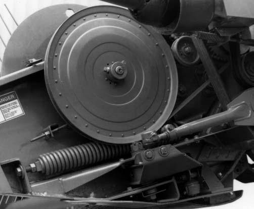
REEL SPEED (Figs. 16 & 17)
The Reel can be operated at five different peripheral (tip) speeds, ranging from 6.3 to 8.7 mph. Normally, the Reel peripheral speed should be about 25% faster than the ground speed. For down and tangled crop, a more even stubble height can be obtained by a higher Reel to ground speed ratio. Exercise the MANDATORY SAFETY SHUTDOWN PROCEDURE (page 8), BEFORE proceeding to adjust the Reel speed.
The Reel speed is changed by adjusting the Variable Speed Sheave, as shown. The Reel speed can be increased by removing Shims from between the Variable Speed Sheave halves and decreased by adding Shims between the Sheave halves. Extra Shims are stored on the outside of the Variable Speed Sheave. To add or remove Shims, perform the following:
1.Derail the Reel Drive Belt from the large diameter Sheave on the Reel Shaft.
2.Loosen (but do NOT remove) all (4) Bolts in the Speed Sheave. Then, remove the Bolt that is on the head of the arrow–shaped Shim.
NOTE: It is NOT necessary to remove the other bolts NOR the outer Sheave half, in order to remove the Shims.
3.The Shims will now slide in and out as shown.
4.After making the Reel speed change, check the Reel Drive Belt tension following details under the appropriate topic in the Service chapter of this

The Release point can be moved toward the Riser Pan (early release) or toward the Conditioner Rolls (late release), by rotating the Cam Track. For best results, the Release point should be 2” above the Riser Pan.
To rotate the Cam Track, it is necessary to loosen (but NOT remove) the (3) Nuts on the inside of the Cam Track. It may also be necessary to raise or lower the Cam end of the Reel, after rotating the Cam. This can be done, following details under the next ”Reel Location” topic.
NOTE: To avoid damage to the Conditioner Rolls and Reel, do NOT allow the Reel Tines to contact the Conditioner Rolls. Furthermore, BE SURE to readjust the Reel Drive Belt tension, after changing the Release Location.
REEL RELEASE LOCATION (Fig.18)
The Reel Release Location is the point at which the Reel releases the crop to the Conditioner Rolls. The Reel Tines will point to the Release Location, as they move past the Conditioner Rolls as shown.
REEL LOCATION (Figs. 19, 20 & 21
The Reel Location is very important to the proper function of the Mower Conditioner. It is very important that the Reel Tines operate as close as possible to the Guards and the Riser Pan, without touching them. This
Reel Location will insure a smooth flow of crop to the Conditioner Rolls. The only time Reel Location should be changed is for conditioning tall and heavy crops.
In down and tangled crops, the Reel will become more aggressive by adjusting the Guard angle to 12 degrees. Conversely, the Reel is less aggressive with a 6 degree Guard angle. Do NOT move the Reel forward and downward as this will allow the crop to build–up on the Riser Pan, causing possible plugging problems and bunchy windrows.
To change the Reel Location, it is necessary to loosen (but NOT remove) the (3) nuts on the inside of the Cam Track and on the inside of the Mounting Plate on the right end of the Header. The Reel can be raised or lowered, using the two Adjustment Bolts shown. After changing the Reel Location, BE SURE the Reel is parallel to the Cutterbar and Conditioner Rolls and, that the Tines do NOT touch the Guards or Riser Pan. The Reel Tines should be located 3/32″ (2.4mm) from both the Guards and Riser Pan, as shown.

NOTE: Always check the Reel Release Location, after changing the Reel Location. In addition, check the Reel Drive Belt tension, after changing the Reel Location, to avoid damaging the Reel and Reel Drive Belt.

The Pushbar can be positioned at five different heights. There is a Plate at each end of the Pushbar that can be move up the Header Frame End Panels. This allows the Pushbar to be positioned above the End Panels for very tall crop conditions. For normal crop height, position the Pushbar in the top two holes of the Header End Panels.

NOTE: Changing the Guard angle or cutting height changes the height of the Pushbar. NEVER attempt to cut with the Pushbar removed as this is an important structural member of the Header and, it protects the Reel.
PUSHBAR ADJUSTMENT (Fig. 21)
The function of the Pushbar is to bend tall crop forward, for butt–first feeding into the Conditioner Rolls. This function of the Pushbar is important to help keep the Conditioner from grabbing uncut crop.
CONDITIONER ROLL PRESSURE (See Figs. 24 & 25)
The Conditioner Roll pressure determines the amount of conditioning done to the crop (assuming the Roll gap is properly adjusted) and should be used accordingly.
For crops like alfalfa and clover (legumes), use only enough Roll pressure to crack and kink the stems. If the leaves show dark spots and/or the tops of the plants are being clipped off, too much Roll pressure is being used. In grass–type crops, more Roll pressure is required than for legume–type crops.
NOTE: If the Conditioner Rolls are separated too far, there is NO amount of Roll pressure that will do a satisfactory job, in most crop conditions.
To adjust the Roll pressure, it is necessary to loosen (but NOT remove) the Jam Nut and tighten or loosen the Spring Bolt, as desired. BE SURE to adjust both Roll Springs (one on each End Panel) the same amount. To speed–up this operation, the Plugs can be removed to accommodate the use of a socket wrench. BE SURE to replace the Plugs after adjustment.
NOTE: Do NOT reduce the Roll pressure to the point where there is NO Spring force on the Rolls. Damage can occur to the Roll Drive Chain, if the Roll pressure is too low, allowing the Rolls to open and close continuously. For operation at low Roll pressures (10 lb/in), completely collapse each Spring and then, extend each Spring 1” (25mm). If the Roll pressure is still too high, increase the gap between the Rolls.
CONDITIONER ROLL GAP (See Figs. 22, 23 & 24)
The Conditioner Roll gap is the distance between the top of the lug on one Roll and the root of the lug of the mating Roll. The Roll gap should be set from 1/16 to 1/8” (1.6 to 3.2mm), for most crops. However, it may be desirable to increase the Roll gap, when cutting thick–stemmed cane–type crops.
NOTE: Always check the Roll gap at several points along the entire length of the Rolls. The gap must always be maintained at a minimum of 1/16” (1.6mm). Operating at closer than this minimum gap or with Rolls touching will result in damage to the Conditioner Rolls, Bearings and Frame.
The Conditioner Roll gap can be changed by adjusting the Stop Bolt at each end of the Header. First, loosen the Locking Jam Nuts. Turning the Stop Bolt into the Roll Arm will open the Rolls and increase the gap. Turning the Stop Bolt away from the Roll Arm will close the Rolls and decrease the gap. BE SURE to adjust the gap an equal amount to both ends of the Header, to keep the Top Conditioner Roll parallel to the Lower Conditioner Roll. MAKE SURE to re–tighten the Locking Jam Nuts after the desired gap has been set.
NOTE: If the Conditioner Rolls are separated too far, there is NO amount of Roll pressure that will do a satisfactory job of conditioning, in most crops.
WINDROW TO SWATH ADJUSTMENT (See Fig. 13)
narrow windrow to a wide swath, by moving the Fluffer up or down. Raise the Fluffer for a narrow windrow and lower the Fluffer for a wide swath. The Fluffer can be adjusted, using the Fluffer Adjustment Handle, as shown. The maximum swath width achievable is 89″ (2260) for the MC2175. Factory windrow width setting will produce a windrow approximately 2′ (610mm). It may be necessary to remove the Windrow Directors to produce a windrow 4′ (1220mm) wide.
BANDED V–BELT TENSION (See Fig. 25)
The Compression Spring, on the Bandbelt Idler, should be set at a 4–1/4″ (108mm) overall length. the Spring–loaded Idler has been designed to protect the Driveline. Overtightening the Idler will decrease this protection. The Spring should NEVER be tightened to less than 3–3/4″ (95mm).

Chapter 8 Lubrication Caution
NEVER attempt to lubricate the machine when any part of the unit is in motion. ALWAYS, BE SURE to exercise the MANDATORY SAFETY SHUTDOWN PROCEDURE (page 8), BEFORE proceeding to lubricate the machine.
It is well to remember that a sufficient amount of oil or grease will prevent excessive part wear and early failure.
Gearbox
NOTE: On a routine basis after every 200 hours of operation, check the fluid level in the Mower Conditioner Gearbox. The level should be maintained with a sufficient amount of EP 90 Gear Lube so that it just starts to run out the Fill Plug opening in the back of the Gearbox.
The Gearbox should be checked occasionally for oil drips and dust accumulation around the Seals. Oil drips or dust accumulation indicate that Seals are leaking. Oil which is tan in color and foams excessively indicates that it has water present. Unless rust spots appear inside the Gearbox, the fluid does NOT require replacement.
NOTE: Do NOT overfill the Gearbox; only fill to the centerline of the Cross Shaft.
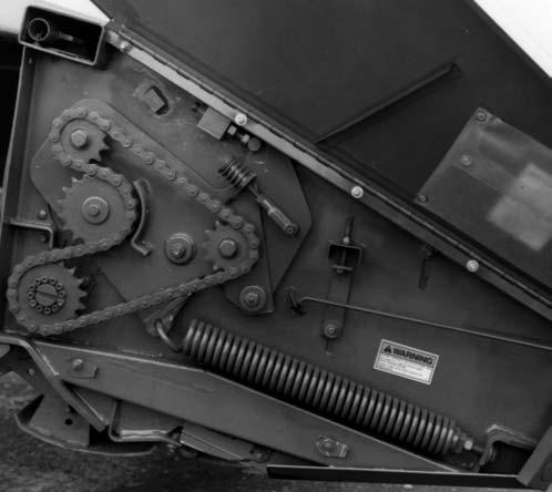
Oiling
Lubricate all Roller Chains every 6 to 8 hours of operation using a good grade of foaming aerosol lubricant, such as NAPA Chain and Cable Lubricant. This type of lubricant increases the life of the Chain 3 to 4 times over those lubricated at 8 hour intervals with new or used motor oil. The recommended method is to spray the entire length of Chain on the center of the Rollers. It is better to lubricate Chains when they are warm (after use, rather than before). An optional Chain Oiler Kit is available. See Optional Features & Accessories chapter for details.
In addition to the Roller Chains, apply oil or foaming aerosol lubricant to the Front and Rear Telescoping PTO Drive Shields.
NOTE: At the end of the harvesting season, coat all of the Roller Chains with oil before placing the Mower Conditioner into storage.
Sealed Bearings
Sealed Bearings are used throughout the machine to provide trouble–free operation, with a minimum of maintenance and lubrication. These Sealed Bearings are lubricated for life and relubrication is NOT required, NOR should it be attempted.
Greasing
NOTE: Grease all fittings on a prescribed basis, at the intervals of operation listed, before and after storing the unit and as otherwise listed. Use a good grade of lithium base grease.
Wipe dirt from the fittings before greasing to prevent any dirt from being forced into the Bearings or pivots. Replace any missing fittings, when noted. To minimize dirt build–up, avoid excessive greasing.
NOTE: In addition to the fittings, inspect and repack the Wheel Bearings at least once a season. The Telescoping PTO Drive should also be separated and grease applied to the splines at least three times during the harvesting season.
Grease Fitting Locations
Grease Every 10 hours (or Daily)
1.Telescoping PTO Drive Crosses (3 Places)
2.Rear Telescoping PTO Drive Tube
3.Wobble Arm Pivot
4.Wobble Arm Socket Bearings (2 Places)
5.Third Link (2 Places)
6.Right Pusharm Pivots (3 Places)
7.Left Pusharm Pivots (3 Places)
8.Right and Left Wheel Leg Pivots (2 Places)
9.Top Roll Chain Drive Idler Pivot
Grease Every 50 hours
10.Banded V–Belt Idler Pivot