5 minute read
CHAPTER 10 PREPARING FOR FIELD OPERATION

TRACTOR & DRAWBAR REQUIREMENTS (Fig. 44)
The tractor, to be used to operate a Mower Conditioner, MUST have: a minimum of 35 hp, a 540 RPM PTO, PTO and hitch dimensions conforming to the ASAE Standard S 203, a remote hydraulic output capable of powering a single–acting cylinder, or two remote hydraulic outputs (if unit is going to be equipped with hydraulic Drawbar Positioner).
Adjust the tractor drawbar to meet the ASAE Standard drawbar dimensions shown. The recommended distances are 15” (380mm), from the ground to the top of the drawbar, and 8” (200mm), from the top of the drawbar to the centerline of the PTO shaft. The distance from the tractor PTO to the center of the hitch pin should be 14” (355mm), to avoid damage to the front Telescoping PTO Drive Shaft.
NOTE: To prevent damage to the Mower Conditioner Telescoping Drive and PTO Tower, avoid making sharp left hand turns while the unit is operating.
CONDITIONER HITCH PLATE POSITIONS (Fig. 45)
The Hitch Plates, bolted to the end of the Mower Conditioner Drawbar (Tongue), should be raised or lowered to make the front Telescoping Drive Shaft as level as possible, when the Header is resting on the ground. Some possible Hitch Plate combinations and attachment positions are illustrated.
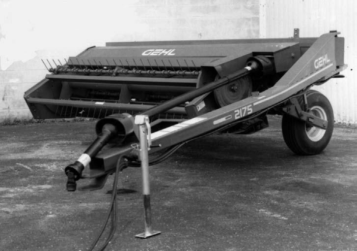
ATTACHMENT TO TRACTOR (Fig. 46)
NOTE: If the tractor is equipped with a 3–point hitch, raise the lower arms to their maximum height (or remove them) to avoid interference with the Telescoping Drive and PTO Tower on the Mower Conditioner.
Attach the Mower Conditioner Tongue to a 540 RPM tractor with a 1” diameter locking hitchpin that has a positive retaining device. After the connection is made, remove the Hitchjack and secure it to the ”Storage Hub” on the top of the Tongue.
1 – 14″ (355mm)
2 – 13″ to 17″ (330 to 432 mm)
3 – 6″ to 12″ (152 to 305 mm)
Fig. 44
Clean and lightly grease the splines on the tractor PTO shaft and the Yoke of the Telescoping Drive. Depress the Safety Lock Ring and slide the Yoke onto the tractor PTO shaft. Move the Yoke back and forth until the Safety Lock Ring locks into the groove in the PTO shaft.
Warning
BE SURE that the PTO Safety Lock Ring is positively engaged and that the Drawbar is securely connected to the tractor drawbar with a Locking Hitchpin, BEFORE starting the tractor engine. Also, BE SURE that the tractor PTO shield is in place and properly secured and that the Telescoping Drive Shields are rotating freely BEFORE starting the tractor engine.
Tongue Positioning
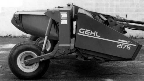
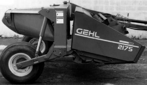
GEHL MC2175 Mower Conditioner is available with two different Tongue Positioning Controls; Hydraulic or Mechanical.
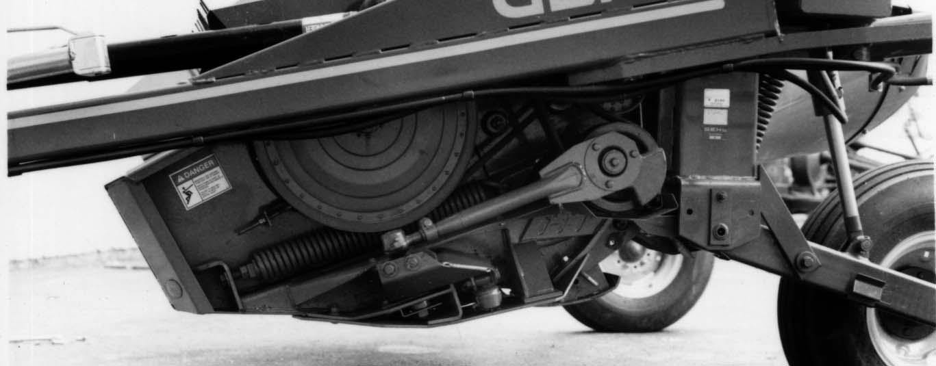
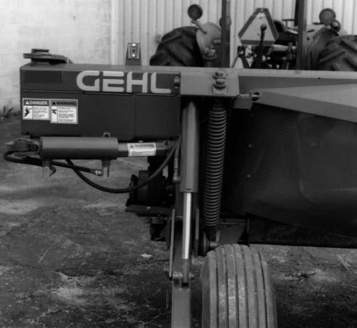
Hydraulic Tongue Control (Fig. 47)
The Hydraulic Swing Tongue Positioner uses a standard 8” stroke, 3” bore hydraulic cylinder (provided) to control the Tongue movement. The Hydraulic Tongue Positioner enables moving the Tongue to any position, from transport to full cutting width, while remaining on the tractor seat. This is extremely useful for steering the unit around obstacles, for finishing narrow strips without running down windrows and, for cutting square corners.

NOTE: Operation of the Tongue Control Cylinder requires a tractor with two remote hydraulic outputs; one for the Tongue Control and another for the Lift Control.
HYDRAULIC LIFT (Fig. 47)
NOTE: The tractor MUST have a remote hydraulic output capable of handling a single–acting cylinder.
Install the appropriate quick–disconnect fitting (to match your tractor connection) onto the Lift Cylinder Hose using Loctite or equivalent pipe sealing compound. Make the Lift Cylinder Hose attachment to the tractor, start the tractor and operate the valve to raise and lower the Mower Conditioner several times to purge the air out of the system.
NOTE: If the Mower Conditioner is NOT horizontal, when it is being raised and lowered, refer to the Service chapter for corrective measures.
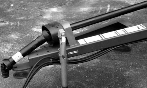
Mechanical Tongue Control (Fig. 48)
The Mechanical Tongue Positioner Control provides two positions for the Tongue. One of the positions is for cutting and the other position is for transport. Activation of the Mechanical Position is controlled by a Rope which is routed to the back of the tractor. To change the Tongue position, pull the Rope to disengage the Positioner Handle from the Notch and drive ahead or back up. As the Tongue starts to move, release the Rope to allow the Handle to engage the desired Cutting or Transport Notch.
BREAK–IN
Before starting to cut and condition, it is recommended that the Mower Conditioner be broke–in, by running it empty for approximately 30 minutes. This initial run–in should be done with the Header on the ground and the Tongue in the cutting position. Before running the unit however, perform the daily (10 hour) maintenance routines listed in the beginning of the Operation chapter.

The Break–in should consist of a twenty five minute and a five minute running period. First, run the unit at idle PTO speed for twenty five minutes. Next, stop the unit and exercise the MANDATORY SAFETY SHUTDOWN PROCEDURE (page 8) before leaving the tractor seat to reinspect the unit. After inspection is complete, reconnect the PTO, restart the tractor, engage the PTO at idle PTO speed and gradually increase the speed to 540 RPM and continue running the machine for 5 minutes. After another inspection, the Mower Conditioner is ready for the field.
TRANSPORTING (Fig. 49 & see Fig. 47)
BEFORE transporting the Mower Conditioner, perform the following:
1.Raise the unit as high as possible with the Hydraulic Lift. Next, position the two Transport Locks (one on each side of the Trailing Leg) up into the locking position. Then, slowly lower the weight of the unit onto the Transport Locks.
2.Move the Tongue to the transport position. If unit is equipped with Hydraulic Tongue Positioner, install the Transport Lock over the Cylinder Rod and secure it with the Clip Pin.
Refer to the Transporting chapter for additional transporting information
Chapter 11 Transporting
TRANSPORT LOCKS (Figs. 50 & 51)
When either model Mower Conditioner is going to be transported on a public highway, BE SURE to raise the unit all the way up and activate both Lift system Transport Locks. For units with a Hydraulic Hitch Positioner, BE SURE also to swing the Drawbar to the Transport position and install the Transport Lock around the extended Positioner Cylinder Shaft.
For units with a Mechanical Hitch Positioner, BE SURE also to swing the Drawbar to the Transport position and make sure it is securely latched.
nylon/plastic tow strap) should always be used to retain the connection between the towing and towed machine, in the event of separation of the primary attaching system. BE SURE to check with local law enforcement agencies for your own particular regulations. NEVER transport the Mower Conditioner at speeds greater than 20 mph. Unless otherwise prohibited, use a Slow–moving Vehicle Emblem.
SMV EMBLEM & REFLECTORS (Figs. 50 & 51)
The Mower Conditioner model is provided with a Slow Moving Vehicle Emblem on the upper left back end of the Conditioner Frame. Red Reflector Strips are also provided at rear corners of the Conditioner Frame.
SAFETY CHAIN & TRANSPORT LIGHTING (Fig. 52) CAUTION
ALWAYS follow state and local regulations, regarding a safety chain and transport lighting, when towing farm equipment on public highways! A safety chain (NOT an elastic or
As required or when desired, Mower Conditioner can be equipped with a safety chain for operation on public highways. A sturdy Chain Loop is welded to the side of the Drawbar to facilitate anchoring the Chain. The safety chain, when attached in this manner, has the following characteristics:
1.Chain is sufficiently slack to allow turns and movements of either the tractor or the farm implement, without placing tension on Chain.
2.Chain is of sufficient strength to hold decoupled implement (and its load) and tow it to the shoulder.