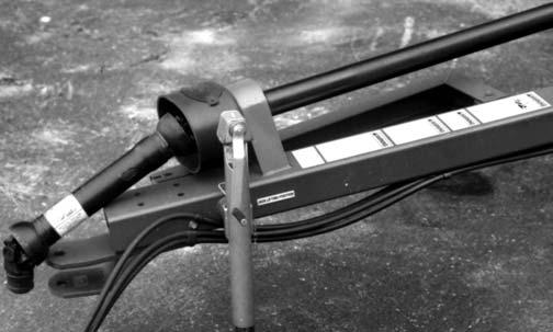
CHAPTER 10 PREPARING FOR FIELD OPERATION TRACTOR & DRAWBAR REQUIREMENTS (Fig. 44)
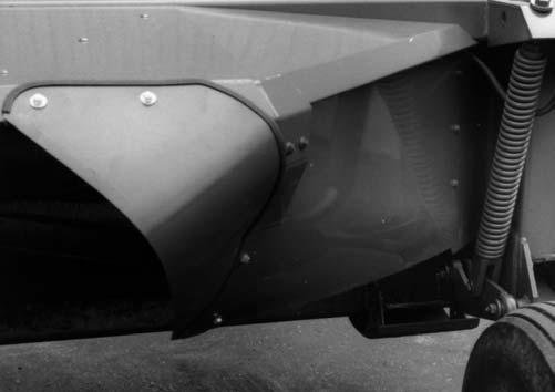
CONDITIONER HITCH PLATE POSITIONS (Fig. 45)
The tractor, to be used to operate a Mower Conditioner, MUST have:
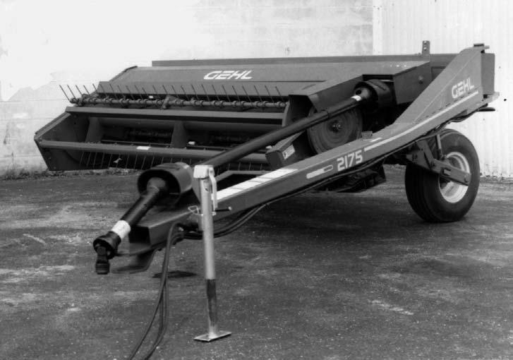
The Hitch Plates, bolted to the end of the Mower Conditioner Drawbar (Tongue), should be raised or lowered to make the front Telescoping Drive Shaft as level as possible, when the Header is resting on the ground. Some possible Hitch Plate combinations and attachment positions are illustrated.
a minimum of 35 hp, a 540 RPM PTO, PTO and hitch dimensions conforming to the ASAE Standard S 203, a remote hydraulic output capable of powering a single– acting cylinder, or two remote hydraulic outputs (if unit is going to be equipped with hydraulic Drawbar Positioner). Adjust the tractor drawbar to meet the ASAE Standard drawbar dimensions shown. The recommended distances are 15” (380mm), from the ground to the top of the drawbar, and 8” (200mm), from the top of the drawbar to the centerline of the PTO shaft. The distance from the tractor PTO to the center of the hitch pin should be 14” (355mm), to avoid damage to the front Telescoping PTO Drive Shaft.
NOTE:
To prevent damage to the Mower Conditioner Telescoping Drive and PTO Tower, avoid making sharp left hand turns while the unit is operating.
Fig. 45
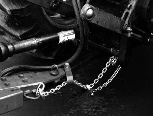
ATTACHMENT TO TRACTOR (Fig. 46) 1 2
3
1 – 14″ (355mm) 2 – 13″ to 17″ (330 to 432 mm) 3 – 6″ to 12″ (152 to 305 mm)
Fig. 44
40
NOTE: If the tractor is equipped with a 3–point hitch, raise the lower arms to their maximum height (or remove them) to avoid interference with the Telescoping Drive and PTO Tower on the Mower Conditioner. Attach the Mower Conditioner Tongue to a 540 RPM tractor with a 1” diameter locking hitchpin that has a positive retaining device. After the connection is made, remove the Hitchjack and secure it to the ”Storage Hub” on the top of the Tongue. Clean and lightly grease the splines on the tractor PTO shaft and the Yoke of the Telescoping Drive. Depress the Safety Lock Ring and slide the Yoke onto the tractor PTO shaft. Move the Yoke back and forth until the Safety Lock Ring locks into the groove in the PTO shaft.