10.10 INSPECTION SERVICING & INSTALLATION OF SUB ASSEMBLIES 10.10.1 Inspection & Servicing the Crank case -
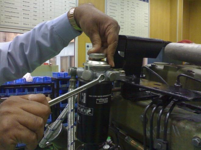
Remove the cylinder liners with tool No. 4H.950.07.0.00. Discard the liner sealing rings. Clean the crankcase and oil passages with clean fuel oil and blow dry with compressed air. Visually inspect crankcase for cracks and other damages. Replace the crankcase if found damaged. Clean the threaded holes by running proper taps. Where holes are blind, apply grease while running a tap. Visually inspect the main bearing bores and caps. Further check the main bores with a dial gauge. Before fitting the main bearing caps for checking diameter, ensure the following : Condition of hollow dowels. Replace damaged dowels if required. Check the crankcase and main bearing cap assembly numbers are the same. Fig.9 -1
Fig.9-1 -
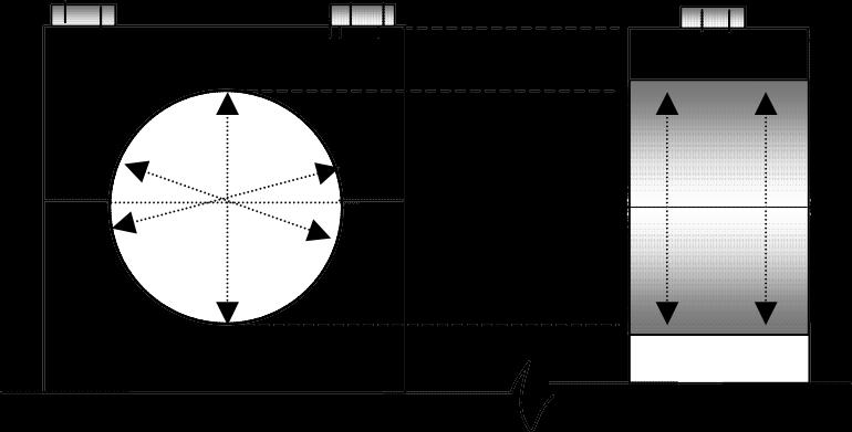
Fit the caps sequentially in the acceding order 1, 2, 3, 4, 5. No 1 starting from the flywheel side. Check the both bearing locating notches on the crank case cavity and bearing caps are on the same side. Tighten cap with new bolts & washers to the prescribed torque. (Refer to tightening torque table) While tightening the bolts take care of the following: Apply oil to bolt threads Apply initial torque with a torque wrench. (Refer to tightening torque table) Torque by angular method in steps. (Refer to tightening torque table) Set dial gauge to the bore’s correct size with a Micrometer. Measure the bores at 2 planes and at 600 angles. Fig.9-2 Record and check values with the specification. (Refer to Specification Data.)
Fig.9-2
50