3 minute read
10.13 Fuel System Setting

Procedure For Priming The Fule Circuit Of Bosch Rotary Fip When The Fuel Circuit Gets Empty
Caution – Please note that the Rotary FIP is lubricated by Diesel, in case of FIP is run dry due to diesel starvation, it could lead to severe damage of FIP internal parts.Always monitor the fuel level in the tank
•Ensure the fuel circuit connections are complete without any leaks or breakage in the hoses and ensure that the suction tube is below fuel level (Completely immersed in fuel in fuel tank)
Priming the Fuel Filter
•Loosen the air vent screw on the main filter
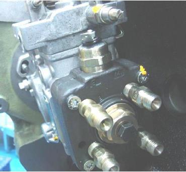
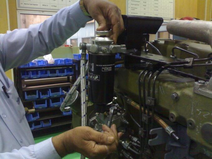
• Start priming by repeatedly pressing the hand primer (Hand primer shown in figure is on filter assembly as in majority application codes, whereas the hand primer location could be different in some cases, please locate the hand primer by checking the fuel line)
•Continue the same till the fuel starts spilling from the air vent screw (This indicates that the air in the circuit is fully vented)
•Screw in the air vent screw and tighten it by hand
•Continue to press the hand primer repeatedly for 5-10 more strokes, tighten the air vent screw to specified (0.9 Kg m) torque
Priming the FIP
•After priming the fuel filter, loosen the fuel return special banjo bolt on FIP, Start priming by repeatedly pressing the hand primer
•Continue the same till the fuel starts spilling from the fuel return banjo (This indicates that the air in the FIP is fully vented)
•Screw in the fuel return banjo and tighten it by hand
•Continue to press the hand primer repeatedly for 5-10 more strokes, tighten the fuel return banjo to specified (2.5 Kg m) torque
Priming the FIP
After carrying out the priming of fuel filter and FIP, the high pressure pipe lines need to be primed in case the engine fails to start
The procedure as follows…
•Loosen the High Pressure cap nuts at injector end
•Crank the engine till fuel splash is seen continuously in all High Pressure lines
•Tighten the HP cap nuts to specified (2.5 Kg m) torque

Fuel Timing procedure for BOSCH Rotary Fuel Injection Pump on R1040, R810 & R1080 Engine (BSIII Engine)
Special tool & Gauge required for fuel timing
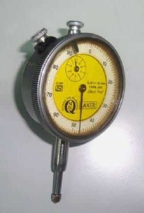
• Dial Gauge (0.01mm least count) Commercially available in Market
• Adaptor for Dial Gauge & Plunger Available at Bosch Authorized dealer, Bosch Part No. F002F31103

•Ring Spanner : 10 -12mm, 13-14mm
•Torque Wrench – 3kg m and 9 kg m capacity
•Long Box Spanner – 22mm, 13mm T Handle long
Procedure of Fuel timing
•Fit fuel pump on Gear Casing, ensure intermediate plate is available below timing lock screw
•Tighten FIP mounting nut at 3Kg m torque

Procedure of Fuel timing
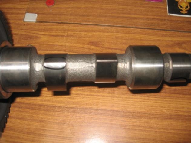
Key way at11 o’clock
•Position the FIP shaft keyway inline with the deliver holder ‘A’ (Keyway at 11oclock position as shown in picture)

Procedure of Fuel timing
Tightness with 2.5 Kg Torque
•Fit Gear mounting flange on tapered key shaft of the FIP
•Tighten the flange mounting nut at 2.5 Kg m torque

Procedure of Fuel timing
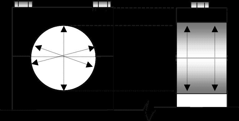
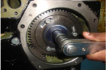
•Take piston of engine cylinder no. 1 (from flywheel end) at compression TDC, align the TDC mark on pulley to TDC pointer

Procedure of Fuel timing

Procedure of Fuel timing
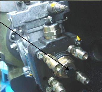
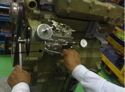
•Fit the adaptor for dial gauge in bleeder screw hole
•Insert the plunger & dial gauge into the adaptor
•Confirm the contact between dial gauge &plunger
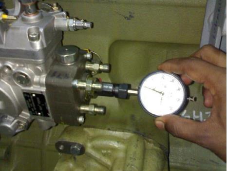
•Hand tighten the nut on adaptor to hold the dial gauge firmly.
Note: Do not apply heavy torque to adaptor
•Rotate the crank pulley in anticlockwise direction till the dial gauge pointer comes to rest
•Set zero on dial gauge
Procedure of Fuel timing
Remove intermediate plate below FIP Lock Screw

Procedure of Fuel timing
•Rotate the Gear mounting flange nut in clockwise direction & note the reading on dial gauge
•When the dial gauge reading corresponds to fuel injection timing (mm of FIP plunger lift @ TDC) lock the timing screw in position.
•
Procedure of Fuel timing
•Fit Gear on mounting flange
•Tighten 3 bolts to 3 Kg m torque. Use hard plain washers below bolt heads.

Procedure of Fuel timing

Procedure of Fuel timing
Insert intermediate plate below FIP lock Screw and tighten the lock screw

Procedure of Fuel timing
Procedure of Fuel timing
Check fuel timing again by –
•Rotating Crank pulley in Anti-Clockwise direction till dial gauge reading comes to zero and
•Again crank pulley to rotate in Clockwise direction aligning TDC mark on pulley to timing pointer and check plunger lift shown on dial gauge is correct as recommended.
•Remove dial gauge, plunger & adaptor for dial gauge. Fit the bleeder screw back in position. Tighten it to 3 Kg m torque.