41 minute read
10.10 INSPECTION SERVICING & INSTALLATION OF SUB ASSEMBLIES

10.10.1 Inspection & Servicing the Crank case
-Remove the cylinder liners with tool No. 4H.950.07.0.00. Discard the liner sealing rings.
-Clean the crankcase and oil passages with clean fuel oil and blow dry with compressed air.
-Visually inspect crankcase for cracks and other damages. Replace the crankcase if found damaged.
-Clean the threaded holes by running proper taps. Where holes are blind, apply grease while running a tap.
-Visually inspect the main bearing bores and caps. Further check the main bores with a dial gauge.
-Before fitting the main bearing caps for checking diameter, ensure the following :
-Condition of hollow dowels. Replace damaged dowels if required.
-Check the crankcase and main bearing cap assembly numbers are the same. Fig.9 -1
-Fit the caps sequentially in the acceding order 1, 2, 3, 4, 5. No 1 starting from the flywheel side. Check the both bearing locating notches on the crank case cavity and bearing caps are on the same side.
-Tighten cap with new bolts & washers to the prescribed torque. (Refer to tightening torque table)
-While tightening the bolts take care of the following:
-Apply oil to bolt threads
-Apply initial torque with a torque wrench. (Refer to tightening torque table)
-Torque by angular method in steps. (Refer to tightening torque table)
-Set dial gauge to the bore’s correct size with a Micrometer.
-Measure the bores at 2 planes and at 600 angles. Fig.9-2
-Record and check values with the specification. (Refer to Specification Data.)
-Inspect cam bores and cam bush I.D. for visible damage and wear.
-With a dial gauge check the Internal diameter of the G.E. cam bush at 2 planes and at right angle. Fig.9-3. Similarly measure the cam bores. Compare the recorded values with the specification. (Refer to Specification Data.) Replace the bush if required.


- If cam bores are damaged replace the crankcase.
Fig.9-3
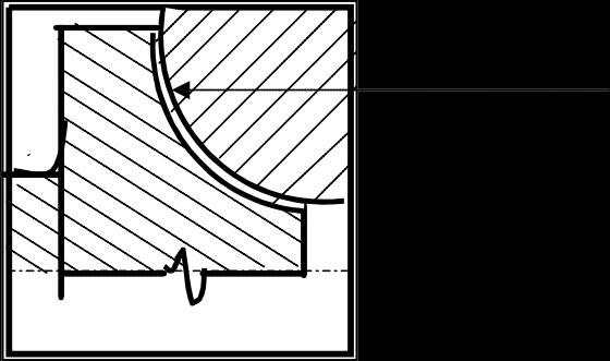
-Fit the old thrust rings to the crankcase and cap and measure total thickness with micrometer. Fig.9-4
-Also measure the distance (W) between the thrust faces of the thrust journal of the crank shaft. Calculate the clearance and check with the specification. If the calculated clearance exceeds the specified limit, then carry out the above exercise with new set of STD thrust rings.
-Inspect the cavity of the liner collar resting face bore in the crankcase .
-Check the condition of lower liner cavity where the liner joint rings sits. If deep grooves are noticed, recondition or replace the crankcase.
10.10.2 Inspection & Servicing the Crank shaft
-Clean the crankshaft before inspecting it.
-Check crank gear for abnormal wear and broken teeth. Replace crank gear if required.
-Check condition of the gear’s dowel pin. Replace if required.
-Support the crank shaft at the outer journals on ‘V’ blocks and check the diameter of the journals and pins. Fig.9-6

-Note these down in the format given below. Compare the readings with the values as specified. (Refer to Specification Data)
-Check the hardness of thejournals and Pins with a non-indenting type hardnesstester. (Rockwell ‘C’scale.) and note these down in the format given below and compare the values with the specifi cation.
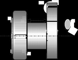
-Check oilsealjournalflangewherethe Flywheelend oil sealfitsforanynoticeablegrooving/ wear, on theoilseal contact zone. Fig.9-7. If groove is deep it may cause oil leakage between the oil seal, recondition the journal.
Oil seal contact zone
-Check the width (W) of No.1 locating journal where the thrust washer contact. If the width exceeds the prescribed limit, machine the faces of the thrust journal’s to the next over size. Fig.9-8
10 10.2.1 Inspection of crankshaft before reconditioning
-The crankshaft’s journals and pins should be checked for cracks by the Magnaflux method, before grinding.
-Remove the balance weights before sending the crankshaft for machining.
-Before removing the balance weights, punch numbers in the ascending order 1-2-3-4 on the balance weights and corresponding crankshaft webs, with No. 1 being nearest to the flywheel. Numbers should be punched on one side of the balance weight and webs for correct repositioning of weights during re-assembly. Discard old balance weight bolts.
10.10.2.2 Precautions during machining
-All journals and pins must be ground uniformly to the same under size diameter and within the tolerance as given in the specification.
-Fillet radius of journals and pins must be maintained as per specification. Fig.9-9 There should be no sharp corners / edges on the journals and pins. These must removed by rounding them off or dimple them.
Fillet Radius

Fig.9-9
- No visible tool marks / scratches should be on the fillet radius or the polished surface areas.
-Oil holes on the journals and pins must be rounded off and polished after completing under sizing. Fig.9-10

Fig.9-10
-Ensure the thrust faces of journals and pins are not machined.
-Locating diameter of flywheel and vibration damper should not be machined.
- As and when required the thrust faces of the thrust journal should be machined (No. 1 Journal) to the prescribed oversize limit.(W) Fig.9-11
10.10.2.3
After grinding
-Inspect the journals and pins diameter with a micrometer. (Refer to Specification Data)
-Inspect hardness of the newly ground journals and pins. (Refer to Specification Data)
-Inspect and ensure that the fillet radius is maintained as per specification. (Refer to Specification Data)
-Check for parallelism between journals and pins. (Refer to Specification Data)
-Inspect and ensure that there are no visible tooling marks / scratches on the fillet radius and the polished surfaces of the crankshaft.
- If oil seal journal flange is reconditioned, check the finish of resting zone.
-Use correct size tap (Refer to tool list 10.5.4) to clean the threaded holes in the crankshaft where balance weight bolts fit.
-Clean the crankshaft and oil passages with clean fuel oil. Remove all traces of abrasive material from the oil passages. Blow-dry with compressed air.
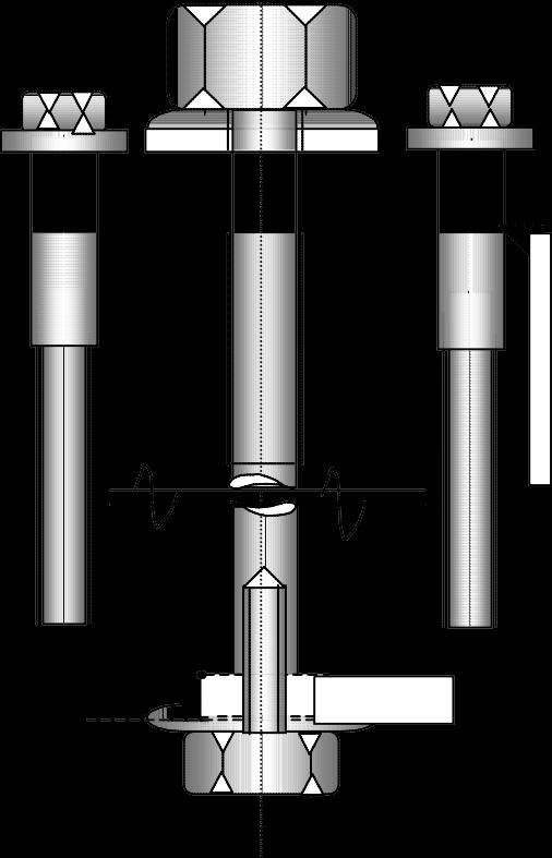
-Balance weight bolts should be replaced at every major Overhaul.
-Refit the numbered balance weights to their respective webs and tighten bolts as per specification. (Refer to tightening torque table.)
10.10.3 Inspection & Servicing the Cylinder Liner
-Visually check the liner condition from inside for excessive wear, step, scratch marks etc.
-Inspect liner externally for pitting etc.
-Check liner’s ovality and taper wear with a dial bore gauge at three planes and at right angles as shown in the Fig.9-12

-Discard the liner if any of the conditions are found not satisfactory and if the wear exceeds the specified limits. (Refer to Specification Data).
Note : When refitting the old liner or replacing the liner, always fit new liner joint rings
10.10.4 Inspection & Servicing the Connecting rod
-Inspect the connecting rod assembly after it is thoroughly cleaned.
-Check the “I section of the connecting rod for notches or hit marks. If the notch is insignificant dimple it out, but if the notch is deep, replace the connecting rod.
-Inspect the connecting rods for parallelism of the small end and the large end bore on a fixture. Replace con-rod if a bend or twist is noticed.
-Check small end bush internal diameter with dial gauge Fig. 9-14 (Refer specification Data). Re place bush if diameter exceeds specified value.
Caution: When pressing new S E. bush, take care to match the oil holes
-Check big end bore for any visible damage. If bore is found damaged replace the connecting rod, do not recondition it.
-Check big end bore diameter with a dial gauge. Fig. 9-15
- If any of the above defects are noticed replace the connecting rod.
-Note: When replacing connecting rod, replace con. rod bolt as per specification.
10.10.5 Inspection & Servicing the Piston
-After cleaning visually check the overall condition of the piston.
-Inspect piston’s crown for surface cracks, burning marks and erosion.
-Inspect the side walls for seizure or scoring marks.
-Inspect piston ring grooves for damage.
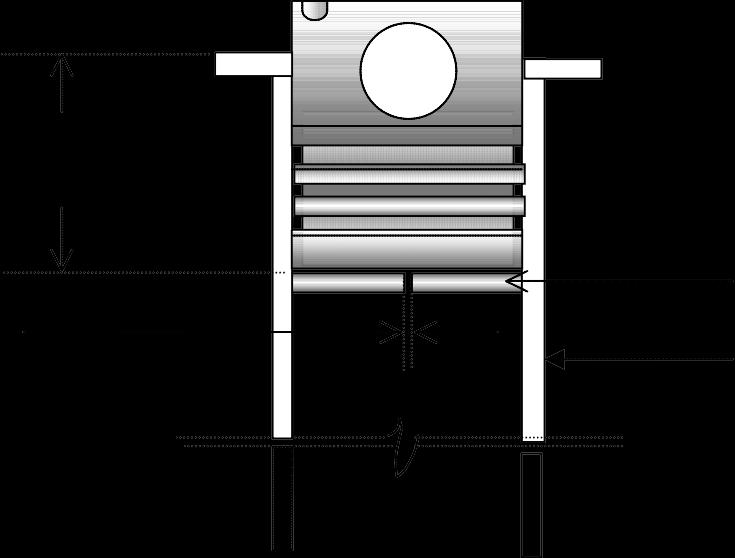
-Check the land clearance between ring grooves and piston ring. (Refer specification Data.) as shown in the Fig. 9-16
- It is recommended to checking land clearance with new piston rings.
-Inspect piston pin bore diameter (Refer specification Data.)
-Check the bore for wear and rubbing marks or other damage.
- If any of the above defect is noticed or if the clearance values do not comply with the specification, replace the piston assembly.
-Inspect piston pin diameter at the center where small end bush fits. Fig. 9-17
-Replace pin if diameter is less than the specified limits. (Refer specification Data)
10.10.6 Inspection & Servicing the Cylinder Head
- De-carbonize the head. Do not use a sharp tool / instrument to scrape off the carbon. Do not scuff or nick the polished surface of the head.
-Clean the Cylinder Head with clean fuel oil. Check the head’s polished surface for flatness.
Fig. 9-18 (Refer to Inspection & Servicing Procedure No.10.10.12)
On turbo-charged engines, check the flatness of inlet and exhaust port seating faces and also the manifolds faces. Fig. 9-19
-Check the distance between valve face and cylinder head face. (valve recess) Fig.9-20 (Refer to Inspection & Servicing Procedure No. 10.10.13)
-Punch numbers on the valve cone according to cylinder numbers, Fig.9-21 No.1 being on the F.W.E. side. Do not disturb the set combination of the valves in their seats. Remove the valves. Discard stem seal.
- De-carbonize and remove the carbon found on the Combustion chamber and in the exhaust ports..
- Replace valve guides irrespective of their condition. (Refer to Inspection and Servicing Procedure No.10.10.14)
- Check valve seat condition in the head. Look for burn marks heavy pitting and other damages.
- If required polish valve seat inserts with proper grooming tool.
-Replace valve seat inserts if beyond repairs. (Individual valve seat inserts can be replaced as re quired)
- Check valve for cracks, burns, erosion etc. Replace damaged valve.
- Check the valve stem diameter. Replace valve, if stem diameter has worn beyond specified limits. (Refer to specification Data )
-Measure free length of valve spring, check for cracks or other damages. Fig.9-22. Replace if re quired. (Refer to Specification Data.)
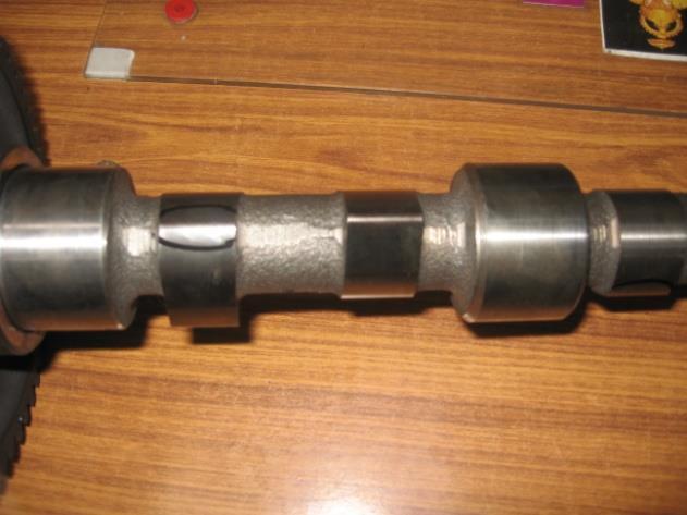
10.10.7 Inspection & Servicing the Camshaft
- Do not separate the cam-gear from the camshaft, as the gear is shrunk fit.
-Check journal diameters with a micrometer Fig.9-23. If journals are worn replace the camshaft with gear.
-Checking cam toes for excessive wear. Replace camshaft and gear assembly if the toe is excessive worn out. Fig.9-24
- Check the thrust washer If found worn or scratched replace it.
10.10.8 Inspection & Servicing the Intermediate gear Assembly
-Check the intermediate gear for wear and damage to its teeth. If wear or damage is severe replace the gear along with the bush bearing.
-Inspect intermediate gear bush Internal Diameter at two places and at right angles in pressed condi tion. If diameter exceeds the specified limits replace the bush.
-Inspect the gear support journal diameter for wear with micrometer at two planes and at right angles Fig.9-25. If wear exceeds the specified limit replace the gear support. (Having a slot for oil supply to auto timer) (Refer to Specification Data).
-Replace the thrust washers.
-Replace the fasteners if found damaged or elongated.
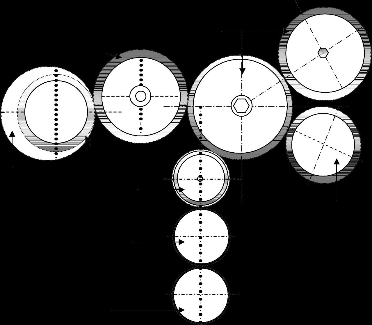
10.10.9 Inspection & Servicing the Lubricating oil pump :
-Remove the back plate from the lubricating oil pump.
-Remove the ‘O’ ring from the groove in the pump body.
-Check end clearance between pump rotor and pump body with a straight edge and a feeler gauge Fig.9-26.If clearance exceeds the specified limit (Refer to Specification Data), replace the pump assembly.
-Inspect radial clearance between the inner and outer rotor all round with a feeler gauge Fig.9-27. If the gap exceeds the prescribed limit (Refer to Specification Data), replace the pump assembly.
-Clean and inspect oil relief valve assembly. If the relief valve plunger is scored and sluggish replace the plunger. Assemble the relief valve with a new split pin..
10.10.10 Inspection & Servicing the Water Pump
-Remove the fan and check the water pump for shaft play and leakage. Even if a slight play or leakage is observed, recondition the water pump.
Note: For reconditioning the pump a mechanical /hydraulic press is essential.
10.10.10.1 Dismantling
-Remove the spacer from the water pump.
-Remove the ‘ V’ belt pulley from the hub.
-Dis-assemble the water pump assembly from the delivery volute casing.
-Support the hub on a suitable support and press the shaft out from the hub. (If difficulty is encoun tered to press the shaft out, heat the hub evenly with a blow torch to about 750 - 800 C. and press the shaft out)
-Press out the shaft and impeller from the bearing housing.
Caution : Do not try to remove the impeller from the shaft unless it is broken, as the impeller will break in the process.)
-Remove the water seal assembly and oil seal from the impeller side of the housing, and discard them.
-Remove the bearing circlip and remove the front and rear bearings along with the spacer. Discard the bearings.
10.10.10.2
Remove the ceramic ring along with the rubber boot from the impeller cavity and discard.
Cleaning and Inspection
-Clean the bearing housing with clean fuel oil.
-Inspect the bearing housing for cracks/ damage. If found damaged replace pump.
-Remove rust, grease and scale formations from the shaft and impeller assembly.
-Inspect the shaft and impeller assembly for cracks, wear or damage. Replace if required
- De-scale and clean the volute casing.
10.10.10.3 Assembly
Note : When reconditioning the water pump replace all parts contained in the repair kit.
-Manually pack grease in to the inner and outer bearings. (Use Lithium based high melting point grease. (~ 1800c )
-Press the inner bearing (small) till it rests in its cavity.
-Insert the spacer. Fill the place around it with about 15-20 gms. of grease.
-Press outer bearing and fit the circlip in the groove.
-Fit the oil seal, the lip facing outwards and visible.
-Fit the new water seal assembly, the carbon face visible.
-Install the rubber boot in the impeller cavity and fit the water seal ceramic ring in it.
Caution : Do not use undue force when fitting the ceramic ring, as it can crack, thus making the sealunserviceable.
-Lightly apply fresh lubricating oil to the water seal’s carbon face.
-Apply soap solution to the shafts boss where the oil seal comes in contact.
-Insert the shaft assembly into the pump housing.
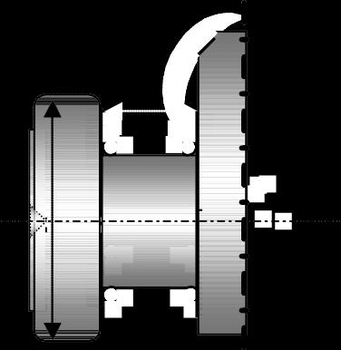
-Check gap between the impeller and the bearing housing. It should be between 0.6 - 0.8 mm
Gap between impeller and housing ( 0.8 mm)
-Press the hub onto the shaft, keeping the hub’s larger boss towards the outside. Press till the hub’s inner face rests on the bearing.
-Check the assembly for leakage and free rotation.
10.10.11 10.10.11.1
Grease the bearings with a grease gun before commissioning the pump. Checking & Servicing the Turbocharger
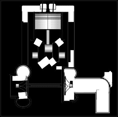
Principle of Operation
-Exhaust gases from an engine which would normally be wasted, is used to drive a turbine and shaft assembly in the turbocharger. On the other side of the same shaft a compressor wheel is fitted. This enables the turbine to drive the compressor, which in turn draws air from the atmosphere and feeds this pre-compressed air to the engine. This enables more fuel to be mixed and burned with a greater mass of charged air and increases the power output from a same capacity cylinder. Better availabil ity of air enhances better combustion, leading to better fuel consumption and less emission.
The advantage of modern turbocharged engine over a naturally aspirated engine with identical power output is as follows :
• Lower emission
• Lower engine noise
• Better torque characteristics.
• Smaller engine and less weight. As a result, turbochargers contribute significantly to the protection of the environment and better utilisation of energy resources
Exploded View of Turbocharger Sk-12

Re conditioning
- The turbocharger must be repaired / reconditioned by authorised KOEL service dealers only, as special tools and expert knowledge is required.
-Before dismantling the turbocharger for reconditioning ensure that the following kit is available.
1. Overhauling kit.
-Tables and charts given at the end of this chapter are only as a guide and reference to the technician repairing the turbocharger.
10.10.11.2 Dismantling
-Mark the turbine and the compressor housing position in relation to the central housing and the back plate. This will help to re-position of housings during re-assembling.
-Clamp the turbine housing inlet flange in a vice. (Vice jaw clamps must be used so as not to damage the flange.)
-Remove the bolts and lock plates of the turbine and compressor housing and discard them.
-Using a plastic or rubber mallet Tap out the housings. (If housing is stuck, treat stuck part with rust remover cum penetrating oil to release housing and remove it.)
Caution : As the turbine and compressor wheels are now exposed, they may get damaged due to improper handling.
-Clamp the turbine locking tool in a vice jaw. Using a ‘T’ spanner loosen and remove the compres sor nut. Discard the nut
Caution: Before loosening the compressor wheel nut check if the nut’s is left hand or right hand threads.
-Using a hand press or even a vertical drill, press out the turbine & shaft assembly from the compres sor wheel.
-Carefully remove the turbine & shaft assembly from the central housing.
-Remove the heat shield
-Remove the sealing (Piston) rings from the turbine & shaft assembly using pliers. Discard them.
-Clamp central housing, across the oil inlet and outlet flange, in a vice and remove the screws hold ing the back plate. Remove back plate. Caution: The Screws are secured with a thread lock seal compound and may be difficult to remove
-Remove and discard ‘O’ ring (big) from the back plate.
-Push out the flinger sleeve from the back plate. Remove the sealing (piston) ring from the flinger sleeve and discard it.
-Remove the sealing ring (small) from the central housing groove and discard it.
-Remove the oil deflector.
-Take out the thrust plate and discard it.
-Pull out the thrust ring and spacer sleeve from the central housing.
-Remove the outer snap rings with snap ring pliers and discard them.
-Remove both the bush bearings and discard them.
- Do not remove the inside snap rings, if they are in good condition and do not have any -wear marks.
10.10.11.3 Cleaning & Inspection of components
- All components should be cleaned with clean fuel oil and dried.
-All traces of carbon and oil residue should be removed from the central housing.
-During cleaning take care and remove the stuck LOCKLITE residues.
-Clean oil passages in the central housing to ensure oil flow to the hot spots and high speed components inside the housing.
-Clean both the turbine and compressor housings by sand blasting (where available) or with clean fuel oil.
a. Central Housing : b. Turbine Housing :
-Check the central housing for cracks or damages.
-Inspect sealing ring area at the turbine side of housing for wear and tear or damage.
-Check the bearing bores in bearing housing for wear / damage.
-Examine condition of snap ring groove in the bearing housing.
-Check the oil passages in the central housing for any foreign material.
-Inspect the condition of the flinger sleeve’s center bore and sealing ring groove.
-Check the sealing area in the back plate where sealing ring fits for wear / damage.
-Replace all worn and damaged components.
-Examine turbine housing for cracks.(Cracks up to 10 mm in length, in only the vicinity of the tongue and partitioning wall are permissible) c. Compressor Housing : d. Turbine wheel & shaft Assembly : e. Compressor wheel : f. Heat Shield :
-Examine housing for scaling in divide wall of gas inlet. If heavy scaling is noticed replace housing.
-Inspect the housing for deformity.
-Replace the turbine housing if any of the above defects are noticed.
-Check housing for rubbing marks - Rubbing traces of 0.02 mm depth are acceptable.
-Check for deformity and any other damage to housing.
-Replace compressor housing if any of the above defects are noticed.
-Examine the shaft for scoring / wear at bearing seating areas.
-Check shaft diameter at bearing areas.
-Check if shaft is true.
-Check sealing ring grooves in the shaft for damage.
-Inspect turbine wheel, for bent or broken blades. If blades are slightly bent at the tips do not try to straighten them as they will break and unbalance the wheel.
-Check turbine wheel tips for burning marks and erosion.
-Check turbine wheels blade edges for rubbing marks.
-Replace turbine & wheel assembly if any of the above defects are noticed.
-Check compressor wheel blades for traces of rubbing.
-Inspect if the compressor’s wheel blades are bent or broken. If blades are slightly bent at the tips do not try to straighten them as they will break and unbalance the wheel.
-Replace compressor wheel if any of the above defects are noticed.
-Inspect heat shield for deformity, cracks or erosion.
-Replace heat shield if any of the above defects are noticed.
10.10
.11.4 Assembly
-When reconditioning the turbocharger extreme cleanliness should be observed.
- All components supplied in the Overhauling kit should be replaced.
-Lubricate and install new bush bearings.
-Fit new snap rings (dish side faces the bearings) in the central housing .
-After bearings are locked in position check the bearings are free in their cavities.
-Install new sealing rings in the grooves of the turbine & shaft assembly.
-Clamp the central housing on a vice jaw with the turbine side facing up.
-Put the heat shield concentrically matching the central bore.
-Lubricate the shaft and rings lightly. Set the piston ring gaps opposite to each other.
-Insert the turbine wheel & shaft assembly into the central housing till the rings rest on the sealing cavity lip. Do not force the shaft in. Rotate shaft once or twice with hand so that the rings centralise in their groove. Rotate again, and while rotating lightly tap the wheel in with the palm of the hand. The rings will slip into the cavity without damage.
-Carefully turn the central housing so the compressor side is facing up.
-Pre-lubricated spacer sleeve and thrust ring and install it onto the shaft and in the housing cavity.
-Lubricate and install a new thrust washer in the housing.
-Fit the oil deflector plate over the thrust washer.
-Fit new ‘O’ ring, (small) with the larger collar on top, in the housing groove. Install new sealing ring in the flinger sleeve groove.
-Install flinger sleeve along with the sealing ring into the back plate central bore. Insert it from the central housing end.
-Lightly coat the new ‘O’ ring (large) with acid proof grease and fit it onto the groove of the back plate.
-Fit the back plate to the central housing. Fit new screws with washers after treating them with LOCTITE 640.
-Measure the turbine contour gap between turbine housing and turbine wheel.
Method :
- Fit the turbine housing to the central housing and fix it with hex screws.
-Place dial gauge pointer on the turbine wheel hub.
-Press hub in, and set pointer to ‘0’.
-Press shaft and wheel against the pointer and note result.
-Remove the turbine housing.
-Heat the compressor wheel to a max. of 1300 C in an oven. Lubricate shaft lightly with oil where the wheel fits. Mount compressor wheel on the shaft and to initial torque.
-Measure contour gap between compressor housing and wheel.
Method :
-Mount the compressor housing to the back plate and bolt it down.
- Fit a dial gauge with the plunger resting on the compressor wheel hub.
-Set the dial to ‘0’.
-Lift the compressor wheel to the max and note the measurement. (Refer table 10.10.11.6) (Basic torque to the shaft nut should be applied within 5 minutes of preheating of the compressor wheel)
-After cooling for about 10 minutes, unscrew the shaft nut a few threads again, apply thread lock adhesive such as Loctite 242 and torque to the specified torque & angle.
Caution: When applying torque to the shaft nut take care that there is no bending effects to the shaft.
-Rotate the shaft to check if it rotates freely and the assembly is correct
Checking axial play Method :
-Place dial gauge pointer on the turbine wheel’s hub face.
-Press hub in, and set pointer to ‘0’.
-Press shaft and wheel from opposite side against the pointer and not the result.
-Lubricate the housing bolts with heat resisting compound such as ‘NEVERSEEZ’ or other antiseize compound and tighten to the prescribed torque
-To store the unit, Cover all oil and air openings
10.10.11.5 TURBOCHARGER TIGHTENING TORQUE
1
1
10.10
.12. Inspecting the cylinder head surface flatness
-Remove and clean carbon from the polished flat surface of the head.
-Check the flatness of the surface.
-Flatness to be checked at 6 places as shown in the Fig.9-33
-Use a 24" straight edge and a feeler gauge to ascertain the flatness of the head as shown in Fig.9-32
(Method.)
-Place the straight edge on the polished surface of the head
-Pass a feeler gauge between the straight edge and the head. (Not under the valve cavities )
- If a feeler gauge thicker than specified passes through the gap, (Refer to Specification Data) the face of the head requires re-facing.
-Correct the flatness by reface the head.
-Using a large thick plate glass smear emery paste over the glass surface. Sprinkle diesel on the paste so that it spread it evenly when refacing. Place the head, face towards the plate and lap. Lap it with a even pressure and length wise, till the high spots are removed. If this should fail to reduce the gap replace the cylinder head.
-This operation can also be carried out in a well equipped machine shop.
- On turbocharged engines the exhaust and inlet manifold seating faces should also be checked for flatness.
10.10.13 Inspecting the Valve recess in Cylinder Head
-Before dismantling the valves check the valve recess. Fig.9-34 The valve recess is the distance between the valve face and the cylinder head face. This can be checked with the help of a straight edge and a feeler gauge. Insert the feeler gauge between the valve face and the straight edge. If the gauge passes through the gap effortlessly, the gap is more than specified. (Refer to Specification Data) In such case. the valve, possibly the valve seat insert or even both the valve and valve seat insert must be replaced.
10.10.14
Replacing valve guides
-Punch out the old valve guide from the valve cavity side of the head with Tool No.03.950.12.0

-Clean the guide bores with a cloth.
-Check the bores for scoring or any other damage.
-Insert the wire snap ring onto the machined guide with Tool No. 4H.950.09.0
-Press the valve guide from cylinder head top with Pressing Tool No. 4H.950.11.0 till the wire snap ring rests on the cylinder head. Fig. 9-35
-With Tool No.4H.950.17.0 Press new stem seals on the guide.
- If the guide bore in the head is damaged and requires to be over sized, semi-finished valve guides are also available for the purpose.
-Note: It is recommended that all bores should be oversized together to the same diameter, even if one or two guide bores are damaged.
Fig.9-35
10.10.15
Replacing Valve Seat Inserts
-Remove the valve seat inserts with the help of a chisel. Take care not to damage the insert bore in the cylinder head.
-Alternatively insert can be removed by cutting it on an appropriate lathe in a machine shop.
-Remove old valve guides
-Clean and remove all burr particles from the bore.
-Note: Inlet valve seat insert and exhaust valve seat insert diameters are different.
-Fit new valve guides. (Refer to Inspection & Servicing procedure No. 10.10.14)
-Cool the valve seat inserts in Dry Ice for about 20/30 minutes or cool in liquid Nitrogen for about 5-6 minutes and fit in the head bore and press it immediately.
-Caution: When using liquid Nitrogen, avoid direct contact with liquid Nitrogen to avoid injury to the body due to its sub zero cooling effect. It is recommended to wear gloves when working.
-Fit inlet valve seat insert with Tool No. 4H.950.13. 0
- Fit exhaust valve seat insert with Tool No. 4H.950.12. 0 Ensure the seats are fitted squarely and completely in the bore.
10.10.16 Assembly of the Piston & Connecting rod
-Apply oil to the piston pin and con-rod S.E. bush
-Install a circlip in one end of the piston pin cavity.
-Assemble the connecting rod to the Piston. Ensure the ‘AC’ mark punched on the piston crown is on the opposite side of the on-rod cap Fig.9-37
-Press the pin into the assembly. (Piston pin is clearance fit and should be fitted by pushing with the thumb and should not be driven by a hammer.
- Fit the second circlip in place
10.10.17 Checking Piston Ring Butt clearance
-Butt clearance, also known as end clearance, is the gap between piston ring ends. This gap is very crucial and should be maintained as specified in the manual. Check Butt clearance with new rings.
Method :
-Insert one piston ring at a time in the liner. To set the ring squarely inside the liner push it down of liner with a piston (As shown in Fig.9.38)
-Measure the gap between ring openings with a feeler gauge..
-Keep the checked rings in the respective liner.
-Follow this procedure with the next set of rings in another liner
-Repeat the procedure with the rest of the rings of the set.
-This way, rings checked in a liner should be installed in that respective liner only.
10.10.18
Checking internal diameter of main and Connecting rod bearing shells
- Main bearings are available in two halves, in finished condition and available in 4 under size. As these are thin walled bearings, they should be pre-loaded in the main bores.
-During fitting, the bearing shells should not be scraped, touched or polished. The bearing shells should only be cleaned in clean fuel oil and fitted. Under no circumstance bearings should be wiped after cleaning.
-Set dial gauge to the correct size (Std or o/s) and measure the bearing ID at 2 planes and at as near the bearing parting line and at vertical Fig.9-39
-Record the values and check these with the specification data.)
10.10.19
Fitting of Piston Rings on Piston
-Before fitting the piston rings in the piston ring groove, ensure the following:
-When installing piston rings, the manufacturer’s name or ‘TOP’ stamped should be facing the piston crown.
-Install correct rings in their proper sequence. (Refer to Fig.9-40)

-Piston rings should be installed with a ring expander, to avoid premature failure.
Oil Control Ring
Fig.9-40
-Ring gaps to be spaced at 1200. Gaps should not be set along the axis of the piston pin, as shown in
10.10.20 Fitting the Crankshaft in Crankcase
-Wipe clean the crankcase main bearing bores and caps where the bearings sit.
- Fit the bearing shell halves in the crankcase bearing cavity and the bearing caps without applying any oil to the bearing back.
-Check bearing shells are fitted correctly and are engaged properly in the locating notches.
-Fit the correct thickness thrust washer in their respective slots provided in the locating bearing bore and cap. (nearest to the flywheel.)
-Wipe the crankshaft journals.
-Lightly wipe the bearings in the crank case. Apply fresh lubricating oil with a brush to the journals, bearings and the and thrust washers.
-Lower the crankshaft in the crankcase.
-Rotate the crankshaft and see that it is free.
-Check the cap numbers, apply oil and fit the caps with dowels.
-While fitting the caps ensure the following: a. The serial number on crankcase and main bearing caps are the same. b. The caps are fitted sequentially in the acceding order 1, 2, 3, 4, 5, No 1 starting from the flywheel side. c. The bearing locating notches on the crank case and bearing caps are on the same side.
-Tighten the main bearing caps as follows : a. Lubricate the bolt threads with engine oil. b. Apply initial torque (See Torque table) with torque wrench. c. Torque the caps starting from centre going outwards. d. Finally tighten by angular method in steps, tightening from the centre cap and going outwards. (See torque table) e. Rotate the crankshaft hand and check it is free and smooth. f. Check the crankshaft end play Fig.9-42. (Refer to Inspection & Servicing Procedure No. 10.10.21)
10.10.21 Checking the Crank shaft end play
- Crankshaft end play can be checked either with a feeler gauge or a dial gauge. For accurate reading the dial gauge is preferred.
-With Feeler Gauge :
To check end play, shift the crankshaft with a lever towards the fly wheel end side. Insert the feeler gauge in the gap at the flywheel end side between the thrust washer and the crankshaft locating journal face and check the clearance with dial gauge.
-Fit a dial gauge with a magnetic base on the crankcase either on the gear side or the flywheel end side Fig.9-42. Push the crankshaft away from the dial gauge with a lever. Set the dial at ‘O’. Again move the crankshaft to wards the dial gauge and take the reading.

10.10.22 Fitting the Piston and Con-rod Assembly in liner
-Select the assembled piston and con-rod assembly. Check the cylinder number punched/ etched on it.
-Set the piston rings gaps at 1200 interval (shown in Fig.9-41). Ensure ring gaps are not be in line with the axis of the piston pin.
-Lightly lubricate piston rings with fresh engine oil.
-Set the ring inserting guide tool (2H.950.02.0.00). onto the piston with rings.
-Remove the con-rod cap from the con-rod keeping the bearing halves in place.
-Wipe the crank pin and cylinder liner. Apply fresh engine oil with a brush to the crank pin and cylinder liner.
-Turn the crankshaft and bring the respective cylinder crank pin to TDC.
-Insert the con- rod from the top of the liner ensuring the ‘AC’ mark on the piston crown is towards the camshaft / tappet side.
-Tap the piston into the liner with a wooden handle, and at the same time guiding the con-rod large end bore towards the crank pin till it snugly fits on it.
-Recheck fitting of the con-rod on to the crank pin.
-Lubricate bearing shell in the cap, Fit the cap taking care that the both bearing notches are on the same side.
-Tighten the con-rod bolts evenly and firmly.
-Follow the same procedure with the other piston / con-rod assemblies.
-After all the con-rods are fitted and tightened, torque the bolts as per specification. (Refer to Torque table)
-Check con-rod is free in its end play.
10.10.23
Valve Lapping
-Before proceeding with valve lapping :
-Check the valve recess is within the prescribed limit. (Refer to Inspection & Servicing Procedure 10.10.13 ) (Refer to Specification Data) If not replace the valve or the valve seat or both valve and valve seat.
-Check condition of both the valve face and the valve seats in the head.
-If the valve face is in relatively good condition only light lapping with a fine lapping paste will be required to ensure a good seating.
- If valve face is damaged, the face will have to be refaced to the correct angle without reducing the rim thickness.
- If the valve rim thickness is already reduced replace the valve
-Also check the valve stem diameter for wear and tear. Replace valve if required.
-Similarly if the seat in the head has to be refaced, the re-facing will be done with a seat grooming tool to the required angle. It is recommended to fit new valve guides (Refer to Inspection & Servicing Procedure No. 10.10.14) before re-cutting or fitting new valve seats.
- If valve seat is damaged beyond repairs replace valve seat. (Refer to Inspection & Servicing Procedure No. 10.10.15)
Valve lapping
-Thoroughly decarbonize and clean the valve and cylinder head before proceeding with valve lapping.
-Apply a small quantity of coarse lapping compound all around the valve seat.
-Dip the valve stem in fresh clean oil and insert the numbered valve it in the respective valve guide.
- Lap the valve and seat by rotating the valve back and forth in a half turn with a gentle but firm pressure by means of a cupped valve-grinding tool.
-After every few turns, lift the valve off slightly from the seat and give it a half turn and tap. This is essential to uniformly spread the grinding paste.
-Keep grinding until the rough gritty feeling of the coarse compound turns relatively smooth.
-Remove the valve, wipe the compound from the valve and seat and check for a contact pattern. When a relatively good flawless pattern is achieved, proceed with the next step and lap the valve again with the fine lapping compound.
-After lapping, visually inspect both valve face and seat. The finished contact pattern on both should be even, without flaw or break, scratch or depression marks Fig.9-44
Note : If a shining line or scratches are visible on the seats after lapping, it is possible that the lapping was carried out with a heavy hand. Such valves will have to again lightly re-lapped with the fine compound.
-Wash the valves and cylinder head with clean fuel to remove all trace of the harmful abrasive material and dry with compressed air.
-Before assembling the lapped valve assembly, confirmed seating is good. This can be ascertained by a ‘pencil erase test’. (Refer to Inspection & Servicing Procedure No. 10.10.24)
-Wipe and lightly lubricate the valve stem. Assemble valve in its original seat with valve spring and new stem seal and lock it in position as shown in Fig.9-45
Fitting sequence of valve assembly
- After locking the valve, check sealing of the seats. This should be checked by carrying out the fuel leakage test. (Refer to Inspection & Servicing Procedure No. 10.10.25)
10.10.24
Valve checking by the Pencil Erase Test
-The pencil erase test is a simple test and should be carried out before the valve is assembled and locked. This test ensures that the valve seat is properly lapped and the sealing is good.
Method :
-Draw a zigzag line on the lapped surface of the valve seat with a soft lead pencil as shown in Fig.9-46
-Fit the valve in its seat in the head. With a slight but firm pressure turn the valve once to 90 degrees or 1/4 turn.
-Remove the valve from the cylinder head and inspect pencil line. The line should be completely erased over the seat Fig.9-47. This proves a proper seating and a good sealing.
10.10.25
Valve checking by Fuel Leakage Test
-After assembling the lapped valves, lock the collar, spring and cone in position with the valve collets. Pour clean fuel oil into the air inlet and subsequently exhaust gas ports.
-Check if the liquid leaks out between the valve face and seat. Fig.9-48
-No fuel oil will leak out between the seats if sealing is effective,
- If sealing is ineffective, fuel will leak out between a valve and seat. This oil leak may be due to dirt on the valve seat. Tap the valve lightly on the stem with a hammer to remove the leak.
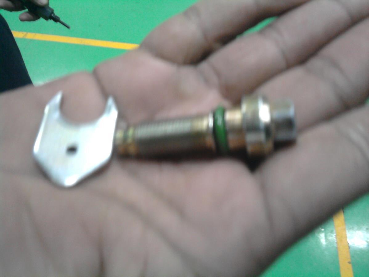
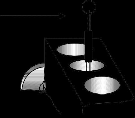
10.10.26 Inspection & Servicing of Oil Spray Nozzles
- It is recommended to check the oil spray nozzle before refitting these back to the engine. Old unserviceable oil spray nozzles should be replaced with new oil spray nozzle.
-The criteria to retain the old nozzles are as follows : a. Min actuating Pressure 0.4 kg/cm2(minimum) b. Min. spray length. 40 mm (minimum) c. Spray angle 50 at 40 mm length (Radius of 25 mm) Above can be checked with the help of a card-board disc.
-Old spray nozzles must be checked before refitting them or this can lead to piston damage.
10.10.27 Checking the Gear back lash
-Back lash is the gap between gear teeth.
-To check gear back lash fit a magnetic base dial gauge on the crankcase face.
-Set dial gauge pointer on a tooth of the gear required to be checked. Fig.9-50

-Engage the gear to one side and set the dial to ‘0’.
-Oscillate the gear back and forth within its free movement.
-Check the reading on dial gauge.
-Repeat this procedure at four places at right angles.
10.10.28 Setting the Fuel Timing
Once the fuel pump is mounted with the Auto timer tightened to the pump shaft, proceed as follows:
-Remove the side cover of the fuel pump.
-Check the position of the plungers inside.
-Using the special spanner turn the fuel pump shaft clockwise till No.1 plunger (first plunger on the fly wheel end side) has started its upward stroke. Fig.9-52
-Rotate the crank shaft till No.1 piston (Flywheel end side) comes on TDC compression stroke. (Check this by rotating both inlet and exhaust push with fingers to find out they are free). If not turn the crankshaft again by another 3600. Also confirm this by checking if the ‘T’ mark on the crank pulley is in front of the pointer. Fig.9-53
-Rotate the crankshaft now in the counter-clockwise direction, till the fuel injection timing mark ‘I’ on the crank pulley is in front of the pointer.
-Remove the delivery valve holder of No.1 plunger. Only take out the delivery valve without the spring.
-Place it in a container of clean diesel to prevent damaging it.
-Tighten the delivery valve holder back firmly.
-Fit a ‘Swan neck’ pipe or a High pressure pipe to the holder. ( The free opening of the pipe should be lower than the fuel pump.
-Connect fuel line to the fuel pump inlet.
-Operate the hand priming pump till fuel start flowing freely the swan neck pipe.
-While still operating the hand pump, rotate the fuel pump shaft slowly in clockwise direction.
-The free flowing fuel should turn to drops and stop completely. Stop rotating the fuel pump shaft.
-This is the exact SPILL CUT OFF point.
-Without disturbing the fuel pump shaft position fit the fuel pump gear to the auto timer and tighten.
-Recheck the timing again.
-To recheck turn the crank shaft counter clockwise till fuel starts flowing out freely again.
-Now turn the crank shaft again slowly in the clockwise direction.
- At a certain point the spill cut happens. Stop turning the crankshaft at this point.
-Recheck the position of the ' I ' timing mark on the crank pulley, it should be in front of the pointer.
-With the timing set, tighten the fasteners of the fuel pump gear fully.
-Fully tighten auto timer shaft nut with the special spanner No.4H.950.09.0 Fig.9-54
-Remove the ‘Swan neck’ or High Pressure pipe.
-Replace the delivery valve and tighten holder to the specified torque.
-Fit and secure the fuel pumps side cover again with its rubber gasket.
10 10.29 Valve Tappet Setting
Firing Order:
1. 3 Cylinder engine 1-2-3 Each Cylinder will come to TDC at 2400
2. 4 Cylinder engine 1-3-4-2 Each cylinder will come to TDC at 1800
Two methods are universally used to adjust tappet clearance in the field. Method -1
-Bring the first cylinder (Fly wheel end side ) to TDC compression stroke. The ‘T’ mark on the crank pulley will coincide with the pointer. Check both inlet and exhaust valves are free and do not move when the crankshaft is rocked back and forth. If not, rotate the crankshaft a full 3600
-Tools required: 6" screw driver, a correct size ring spanner and a correct thickness feeler gauge.
-Set the gaps on both the inlet and the exhaust tappets of the cylinder as specified (See specification data.) The feeler gauge should slide firmly but freely in the gap.
-Turn the pulley in the clockwise direction till the next cylinder in firing order comes to TDC com pression stroke. Continue with the process till all the cylinders are covered and all tappets are set.
Fig.9-55
Method -2
This is a relatively simple and less time consuming method. In this method, multiple tappets can be set in one position of the crankshaft
Position 1
With cylinder No.1 in TDC compression position, set the following valves:
3 Cylinder engine.
Cylinder No.1 Inlet Exhaust
Cylinder No.2 - Exhaust
4 Cylinder Engine.
Cylinder No.1 Inlet Exhaust
Cylinder No.2 Inlet -
Cylinder No.3 Inlet - Cylinder No.3 - Exhaust
Cylinder No.4 - -
Position 2
Rotate the crankshaft one full rotation (3600) and again bring No 1 cylinder to TDC position. The engine is now at TDC with both valves in overlapping position and are not free to rotate. In this position set the following valves. Refer to Fig.9-56
Cylinder No.1 - - Cylinder No.1 - -
Cylinder No.2 Inlet - Cylinder No.2 - Exhaust
Cylinder No.3 - Exhaust
Cylinder No.3 Inlet -
Cylinder No.4 Inlet Exhaust
Note: Valves can be set at whatever position the crankshaft comes first as shown in the below sketch.
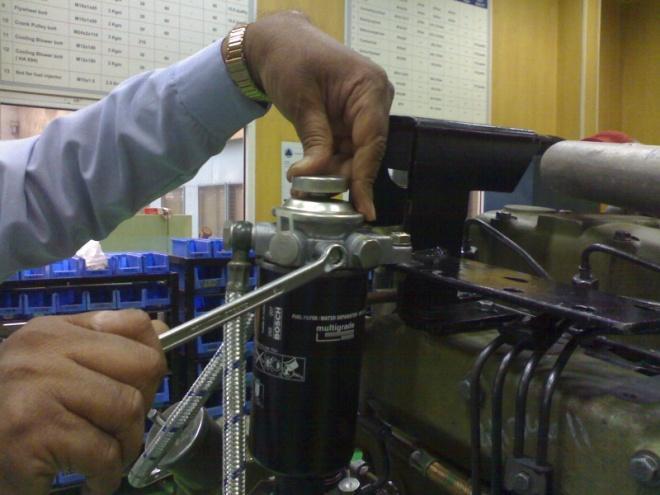
10.10.30 Servicing Spin -On type lubricating oil filter
-The spin-on filter should be replaced at every oil change, or whenever the oil is changed for any reason.
-Unscrew the filter cartridge with a strap tool in the counter-clockwise direction. (Strap Tool is commerciallyavailable)

-Remove the cartridge and destroy it.
-Clean the sealing surface of the filter carrier with a dry cloth.
-Apply a light film of oil with a brush to rubber seal of new cartridge.
-Screw cartridge into place by hand till the seal is evenly seated.
-Tighten the cartridge firmly by giving half a turn.
10.10.31 Bleeding the Fuel System
-Before starting the engine the fuel system should be bleed thoroughly. All air should be removed or it will affect the engine’s performance.
-Loosen the vent screw given on the pre-filter’s head. Operate the hand priming pump till fuel flows freely out without any air bubbles. Retighten the vent screw.
-Similarly loosen the vent screw on the micro filter head and carry out similar operation.
-Where vent screw is provided on the Fuel pump carry out similar operation.
10.10.32 Inspection & Servicing the oil cooler :
The oil cooler is a stainless steel disc type plate cooler. It is located in a cavity provided in the lubricating filter header. In normal condition servicing for the plate type oil cooler is not required, but if the cooler is removed for any reason then it has to be serviced. To approach the cooler, it is necessary to dismantle and remove the filter header.
Servicing :
-Remove the cooler from the header by removing the set bolt and special washer. Fig.9-57
- Plug the coolers oil inlet and outlet openings.
-Clean the cooler externally with soap water/Petrol to remove rust etc from it. Caution: Do not use acid based or alkaline based cleaners. Refrain from using sharp instrument as this may damage the cooler.
- In a bowl of clean fuel oil dip the cooler element after removing the plugs. Clean the oil side of the cooler by vigorously shaking the element in the fuel. With the cooler still dipped in fuel oil direct compressed air very slowly from the oil outlet to clean the inside of the cooler by agitation method. Rinse it twice in clean fuel oil and flush it with fresh Lubricating oil.
-Install the cooler back in the header with new joint, and torque as specified.
10.10.33
Inspection & Servicing of the Radiator
-Disconnect radiator from the engine.
-Discard all old hoses.
-Check the radiator cap and replace if required.
-Check radiator core for tube leaks, and damaged fins. Have these repaired.
-Also check for leaks which usually take place between the soldered joints of the core and header tanks, and water inlet & outlet connections where the hoses fit.
Caution : It is not recommended to manually clean the radiator. As this causes damage to the radiator core (cooling tubes) and renders the tubes unserviceable.
-Radiators should be cleaned with specially formulated radiator cleaning compounds.
- It is advisable to carry out cleaning of the radiator while mounted to the engine, as this way both the radiator and the engine’s water jacket are cleaned.
-Cleaning should be carried out strictly as per instructions of the cleaning compound manufacturer.
Radiator Cap
Top Header Tank
Core (Tubes & Fins)
Connection.
Bottom Header Tank
10.10.34 a.) Battery :

Inspection & Servicing of Auto Electricals
-Disconnect the battery from the engine.
-Fully charge the battery and keep it in a dry place on a wooden plank b.) Alternator : c.) Starter :
-After every 30 days recharge the battery on a low charge.
- On a reconditioned engine fit a fully charged battery, as the engine will initially draw more current during cranking and will also take a longer time to start.
-Disconnect and remove the alternator from the engine and have it reconditioned by an Authorized Auto Electrical Dealer.
-Under no circumstance short the leads of the alternator to see that it is developing current, as this will damage the alternator.
- Disconnect and get the starter repaired / reconditioned by an Authorized Auto Electrical Dealer.
Oil Seal Fitment.
PTFE oil seals are used on R1040 engines instead of conventional rubber oil seals. These are the ‘DoubleLip Oil Seal’, one lip for preventing dust damaging the seal and shaft and the second lip to prevent oil coming out. The oil seal is very effective and will reduce wear and tear to engine components if installed properly The fitting instructions given in Servicing Procedures 10.10.35 and 10.10.36 must be strictly followed to avoid future problem with the oil seal.
10.10.35 Fitment procedure for the F.W.E. Oil Seal
Note: IT IS RECOMMENDED TO USE OF A MECHANICAL OR HYDRAULIC PRESS TO FIT THE F.W.E. SEAL DO NOT APPLY OIL TO THE SEAL OR SHAFT. OIL SEAL SHOULD BE INSTALLED DRY.
-Clean the oil seal bore in the housing with a clean dry cloth.
-Place the oil seal housing on a clean surface under the press.
-Remove the oil seal from its packing and install immediately.
-Locate the oil seal by hand on the entry chamfer of the housing.
-Place the inserting mandrel flat on the seals metallic face.
-Press the oil seal under a press, till the mandrel rests against the housing’s face.

-Remove the mandrel.
Sleeve Tool :
-Fit the seal sleeve tool over the installed oil seal from the oil seal’s steel casing side. Ensure both the dust seal and oil sealing lips are positioned correctly on the sleeve.
-Wipe the crankshaft’s oil seal journal flange with a dry clean cloth.
-Locate the housing assembly, with the oil seal and sleeve to the crankshaft journal flange.
-Press the assembly to the crankcase till the dowels are engaged.
-Pull out the sleeve Seal tool.
-Fasten housing to the crankcase
10.10.36 Fitment Procedure for G.E. Oil Seal
Note : DO NOT APPLY OIL TO THE SEAL OR THE PULLEY. OIL SEAL SHOULD BE INSTALLED DRY.
-Clean the oil seal locating bore in the Gear Cover.
-Remove oil seal from its packing and install immediately.
-Locate the oil seal by hand on the oil seal mandrel (4H.950.21.0.00)

CAUTION : DO NOT APPLY ANY OIL TO THE SEAL OR HOUSING
-Place the inserting mandrel flat on the gear cover face.
-Fit the locating bolt on crankshaft G.E. side.
-Hammer the oil seal untill the mandrel stops against the gear cover face.
-Wipe the pulley and insert immediately in dry condition.
-Fasten the crank pulley bolt
G.E. Oil Seal Pressing Mandrel
10.10.37 Servicing Oil Bath Type Air Cleaner
Oil bath air cleaner should be serviced before refitting to the engine.
-Dismantle and separate the oil bath from the oil cleaner body.
-Drain out old oil from the oil bath and clean the bath with fuel oil and wipe it dry.
-Check and discard the old sealing rings and washers.
-remove the primary wire mesh element from the body and clean it in a soap & water solution. Final cleaning should be done by water pressure from the opposite side till all sediment is removed from the element. Dry it properly.
-Also clean the air cleaner body along with the secondary wire mesh element into a trough of soap water solution.
-To clean pass compressed air at high pressure with water from the air outlet side. Air passed with water causes water to agitate. It is by this method of back flushing the element will be cleaned. Continue till air bubbles flow out freely from the inlet of the air cleaner.
-Clean the air cleaner body with plain pressurized water about twice to remove all trace of soap.
-Dry thoroughly with compressed air.
- Fit new sealing rings and seal washers.
-Fit the air cleaner body to the engine.
-Fill fresh Lubricating in the oil bath, up to the oil filling mark.
-Fit the bath to the body and clamp it.


10.12 TROUBLE SHOOTING
12-1. Engine fails to rotate :
12.2. Engine rotates slowly during starting:
-Battery run down.
-Defective Starter
-Loose /dislodged battery cable.
-Engine used after a long period
-Engine seized.
-Battery weak
-Battery cable loose
-Faulty starter
-Small capacity battery
12.3. Engine rotates, but does not start :
- No Fuel in tank
-Fuel Quality poor
- Air in Fuel line
-Leaking Fuel line.
-Fuel line clogged.
-Fuel filter clogged
-Incorrect control lever setting
-Fuel pump defective
-Incorrect fuel timing
-Incorrect tappet setting.
-Cylinder head gasket blown
-Engine not used for a long time
-Worn /damaged piston rings
12.4. Engine has Starting Difficulty:
-Clogged /Dirty air cleaner
-Poor quality Fuel
- Air in fuel line
-Incorrect valve and fuel timing
-Faulty fuel injector
-Engine used after a long period
-Leaking engine valves
-Broken / worn piston rings
-Engine needs decarbonising
12.5 Engine starts but stops after some time:
-Fuel tank cap vent hole blocked
- Air cleaner choked
-Engine has run out of fuel
- Air in fuel line
-Fuel filters choked
12.6. Engine Lacks power:
12.7. Engine misfires during operation:
-Fault in fuel pump
- No water in radiator.
-Gasket blown
-Engine Piston / liner seized
-Engine bearing seized
-Engine needs overhauling
-Choked /Dirty air cleaner
-Faulty air cleaner hose.
-Excessive exhaust back pressure
- De-rating not calculated
-Fuel quality poor.
-Choked fuel line
-Choked fuel filters
- All cylinders not firing
- Loose H P Connection
-Fuel injector faulty
-Water and fuel mixed.
-Incorrect valve and fuel timing.
-Leaking engine valves
-Faulty turbocharger
-Broken / worn piston rings
-Worn out Liners
-Damaged main and CR bearings
-Faulty Governor setting
-Improper alignment with driven unit
-Engine has come for Overhauling
-Engine used after a long time
- Air in fuel line
-Faulty Injector
-Water mixed with fuel
-Faulty fuel pump
- All cylinders not firing
-Incorrect valve setting
12.8. Engine does not reach its governing speed:
-Choked Fuel filters
-Choked fuel line
-Control lever setting incorrect
-Engine over loaded
12.9. Engine speed does not remain constant:
-Choked Fuel filters
-Choked fuel line
12.10
-Faulty injectors
-Faulty Fuel pump
-Faulty governor adjustment
-Excessive governor linkage play.
-One or more cylinders not firing.
-Choked air cleaner
-Fuel timing incorrect.
-Incorrect injector pressure
-Faulty/ dribbling nozzle
-Defective fuel pump
-Incorrect tappet setting
-Low compression
-Incorrect valve timing
-Valves leaking
-Stuck /broken piston rings
-Worn piston rings and liners
-Worn out main / con-rod bearing
-Incorrect fuel pump setting
-All cylinders not firing properly
-Faulty turbocharger.
-Engine needs overhauling
12.11.
- Air cleaner choked
-Derating not considered
-Poor quality of fuel
-Control lever not properly set.
-Faulty injector
-Incorrect fuel setting
-Fault in Fuel pump
-Engine over heated.
-Engine overloaded
-Valve spring broken
-Incorrect Tappet setting
-Broken piston rings.
-Crankshaft end play excessive
-Damaged bearings
-Damaged valve guide and valve
- All cylinders not firing properly
-Turbocharger sluggish.
-Engine requires overhauling
-Choked air cleaner
-Excessive exhaust back pressure
-Faulty injector
-Retarded fuel timing
-Incorrect grade of lub oil used.
-Dirty choked oil suction strainer
-Prolonged oil change period
- Lub oil dilution
-Choked lub oil filter
-No coolant in radiator
-Clogged Radiator
-Faulty thermostat element
-Fan inadequate
-Engine overloaded
- Tappet setting incorrect
-Improper alignment with driven unit
-Broken piston rings.
-Excessive crankshaft end play
-Damaged bearings
-Damaged valve guide and valve
- All cylinders not firing properly
-Turbocharger not functioning .
-Dirty air cleaner
-Excessive exhaust back pressure
-Fuel quality poor.
-External fuel leakage
-Wrong Fuel timing
-Faulty Injectors
-Faulty Fuel Pump
-Overloading of engine
-Incorrect tappet setting
-Damaged Piston rings & liners
-Excessive Carbon build up in the combustion chamber
-Bearings wear beyond specification
-Engine needs overhauling
-Wrong grade of lub oil
-Excess oil in the sump.
-Over filling the Oil in air cleaner
- TC seals leaking
-Worn Piston and Liner.
-Worn out Valve stem and guide
12.15. Engine gives out white smoke:
-Water mixed with Diesel
-Water entering the combustion chamber
12.16. Mixing of Diesel with Lub. oil:
-Faulty fuel feed pump
-Dribbling Injector nozzle
-Broken piston rings
-Worn piston & liner
- All cylinder not firing properly
12.17. Excessive lub. oil consumption:
-Wrong brand of lub oil
-Wrong grade of Lub oil
-Excess oil in the sump.
-Idling for prolonged period
-External oil leakage.
-Engine overheats
-Worn T/C oil seals
-Worn Piston rings & Liner
-Worn valve and Guides.
12.18. Low Lub Oil Pressure:
-Oil change overdue
-Wrong brand and grade of oil
-Wrong grade of Lub oil
-Choked suction tube
-Choked oil cooler
- Lub oil dilution
-Choked oil filter
-Choked oil passages
-Faulty oil pump
-Faultypressure regulating valve
-Defective by pass valve.
-Over loading of engine
-Over heating of engine
-Incorrect tappet setting
-Incorrect Fuel timing
-Worn main bearings
-Engine need overhauling
12.19. Fast bearing wear:
-Prolonged oil change period
-Fuel Dilution with oil
-Poor quality of oil
-Oil starvation due to a) Choked suction strainer
12.20. Excessive Piston ring and liner wear: b) Choked filter c) By-pass valve remains open
-Water dilution with oil
-Oil level in sump low
-Overloading the engine
-Bearing Seizure
-Dust entry from air intake system
-Poor quality of fuel
-Wrong grade of lub oil
-Prolonged oil change periods
-Dirty oil filter
-Over heating
-Engine Overloading
-Broken piston rings
-Piston & liner seizure
12.21. Excessive Valve & Valve guide wear:
-Dust entry from air system
-Poor quality of fuel
-Wrong grade of lub oil
-Prolonged oil change periods
-Dirty oil filter
-Over heating
-Improper lubrication at rockers
12.22. Valve spring breaking:
-Water contamination with oil
-Pitted valve spring.
-Engine re-commissioned after a long time.
-Engines Preservation not done
-Worn out valves and valve guides
12.23. Fuel Injection equipment wear excessive:
-Poor quality of fuel
-Filter element used of poor quality.
-Water contamination with Fuel
12.24. Diesel Knock:
-Diesel quality not as recommended
-Fuel timing far advanced
-Injector pressure setting high.
-Incorrect valve timing
-Wrong specification high pressure pipe fitted.
12.25. Mechanical knock :
-Incorrect tappet setting
-Broken piston ring
-Excessive clearance between the piston pin and piston pin bore.
-Excess clearance between piston and liner
-Excessive clearance in Con rod bearing.
12.26. Excessive Vibration:
-All engine cylinders are not firing
-Faulty engine mounting
-Mounting bolts loose
-Improper exhaust clamping
-Alignment with driven machinery incorrect
12.27. Battery runs down frequently:
-Check battery condition.
- Fan belt loose
-Dynamo / Cut out defective
-Alternator defective.
-Defective wiring.