2 minute read
Transport on public roads


9.1.3 Transport on public roads
Caution!
To prevent the raised rotors being lowered accidentally during road travel and consequent danger to other road users, the tractor's hydraulic control lever must be locked against inadvertent operation. – Secure the tractor's control lever against inadvertent operation. While the tractor's engine is running, there is a risk of injury due to functional faults or external operation of the machine. – Before leaving the tractor: • Switch off the engine. • Remove the ignition key.
Caution!
Observe the following max. road speeds: – Swather with brake system: 50km/h – Swather without brake system: 25 km/h – In road bends and on poor road surfaces: max. 20 km/h
Adapt your driving speed to the traffic and road conditions. Reduce your speed when approaching a bend. In other countries, lower max. permissible road speeds may apply. The following max. road speeds may never be exceeded:
The following conditions must be met for road transport: • The tractor's front axle must always be loaded with at least 20 % of the tractor's empty weight –see Ballast weights, page23. • The machine must be hitched to the tractor completely and correctly –see Hitching the machine, page29. • The machine must be in the transport position –see Transport position with ISOBUS Terminal, page50 or Transport position with operating terminal, page53.
1
2
3
68068
8 4
65414
5 6
7
• Rear lighting bracket must be swung downwards. –If necessary, remove the fixing screw(1), and swing the warning plates(2) downwards. (Fig.1)
1
• Swing up the outer guard frames(3). (Fig.2)
2
3
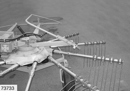
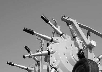
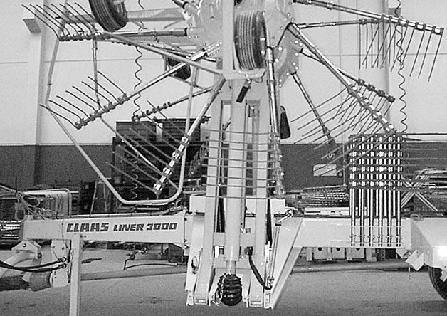
• Preparing the front rotors: – Before raising the rotors, the outer tine arms must be removed. • Remove the outer tine arms from their mounting tubes, and insert them in the racks(7). • Seal the ends of the mounting tubes.(Fig.3) Also observe the instructions in Parking the machine at sub-zero temperatures, page45. – On raised rotors, the outer tine arms(5,6) (Fig.4) must also be removed. • When the rotors have been raised, remove the outer tine arms(5,6), and insert them in the racks(7). – From Serial No. 605 0 1858, the spring brackets of the tine arms removed must be hooked into position –see Removing the tine arms, page55. (Fig.3,4)
4
8
9
10
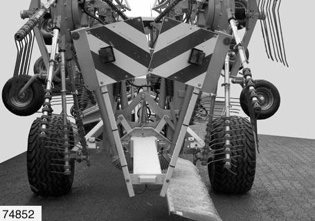
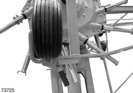
– With raised rotors, the lower contour wheels(8)(Fig.4) must be swung upwards. • When the rotors have been raised, swing the lower contour wheels(8) (fig.5) upwards, and lock them in position with lever(9). (Fig.4,5)
(Fig.6)
5
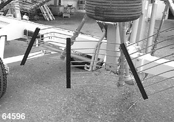
Danger!
Risk of injury from projecting machine parts. – Tine guards(10) must be fitted to the tines facing outwards.