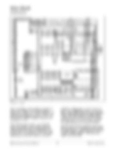
Drive Circuit Control Circuit
E366
Drive Control Circuit
With the actuation circuit complete, the logics supplies a HIGH voltage (15 volts) to the direction switch at P1-11 and P1-12. A HIGH voltage is also supplied to the accelerator control at P1-10, P1-9, P1-8 and P1-7. Battery voltage is supplied to the accelerator at P1-9.
accelerator voltage pattern on P1-7, P1-8, P1-9 and P1-10 to change from all HIGH to one of the fifteen speed patterns explained under Accelerator Control. The logics detects the voltage pattern change at P1-7. P1-8, P1-9 and P1-10, activates the correct direction contactor, regen contactor and starts pulsing the drive power transistors.
Releasing the park brake closes the park brake switch and provides a path to battery negative. Selecting a direction with the service brake OFF (switch closed) will change the voltage from HIGH to LOW on P1-12 for forward or P1-12 for reverse. Depressing the accelerator pedal will cause the
MicroCommand Control System
With the forward direction selected, current flows from the logics P2-17 through the forward direction and regen contactor coils to logics P2-13 and P210 back to battery negative. The forward and regen contact tips close.
41
Systems Operation


