2 minute read
DC-DC Converter


2. Turn the key to ON and release the parking brake.
3. Select a direction and rapidly depress the accelerator pedal all the way to the floor.
4. Measure and record the time it takes the bypass contactor to close. This should be 1.0 to 2.5 seconds after the accelerator is fully depressed.
5. If the recorded value from Step 5 is less than 1.0 seconds, the logics may need to be replaced. (During normal operation, this time will vary with the load on the truck.)
6. If the recorded value from Step 5 is more than 2.5 seconds, check the bypass contactor tips for free movement. Check wiring for bad connections.
NOTE: The bypass contactor will not close if the accelerator linkage is not adjusted correctly. It also may not close if programmable feature “5” (Top Travel Speed) is not set to maximum.
Contactor Components
WARNING
Battery voltage and high amperage are present. Injury to personnel is possible. Disconnect the battery and discharge the head capacitor (HEAD CAP) before any contact is made with the control panel.
Coil Resistance
1. Disconnect the battery and discharge the head capacitor.
2. Disconnect all leads to the X and Y terminals of the coil.
3. Set the multimeter to 200 ohm range.
4. Measure the resistance of the coil at the X and
Y terminals. It must be within specifications.
See Component Measurements in the
Specifications section.
5. If the coil is not within specifications, the contactor assembly will have to be replaced.
Coil Pulsing
1. Disconnect the battery and discharge the head capacitor.
2. With the contactor coil leads connected, set the multimeter to the 200 volt DC range.
3. Connect the multimeter negative lead to the negative coil terminal Y and the meter positive lead to the coil positive terminal X wire #38.
4. Connect the battery and activate the controls necessary for the contactor to be activated.
5. After the contactor activates, the multimeter must indicate 18 to 35 volts. If the voltage is not correct and the contactor passed the Coil Resistance test, the logics must be replaced.
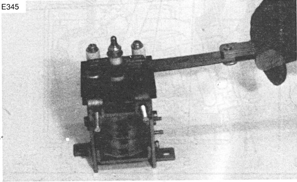
Contactor Tips
E345
Checking Contactor Tip Gap
1. Disconnect the battery and discharge the head capacitor.
2. Visually inspect the tips to verify that they are not welded, melted, burned or pitted.
3. Press and release the tips quickly to verify that there is no bonding.
4. Visually inspect the contactor assembly. Verify foreign objects don’t interfere with normal contactor operation.
5. Check contactor tip gap with a feeler gauge as shown. Refer to the Specifications section for correct settings.