3 minute read
Lift Circuit
Pump Control Circuit
D4P is a flyback diode for the hydraulic pump motor circuit. This circuit uses the current created by the collapsing magnetic field of the field windings in the pump motor to keep current flowing when transistors T1P, T2P and T3P are OFF. When T1P, T2P and T3P are OFF, all current from the field goes through PD2, D4P, PA1 and the pump motor armature (ARM) back to the field. When T1P, T2P and T3P are pulsing, the flyback circuit causes the average pump motor current to be greater than the average battery current through T1P, T2P, and T3P.
The steering system is self-compensating for battery voltage. The logics will increase the “on-time” of T1P, T2P and T3P when the battery voltage changes.
Lift Control Circuit
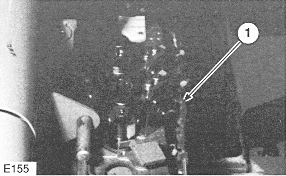
E155
Location of Components (1) Valve control card.
The M80D lift truck is equipped with a seven speed lift system. The system is controlled by a valve control card (1) mounted at the top of the control valve. The valve control card uses a Hall-effect transducer (LIFT SENSOR) and a magnet to sense lift lever movement. The closer the magnet is to the transducer, the greater the pump motor speed.
E204
Location of Components (2) Lift sensor. (3) Magnet. Lift Control Circuit
NOTE: Shaded lines illustrate current flow in the circuit diagrams. Other circuits can be activated at the same time, but each one is shown separately to illustrate current flow in each individual circuit.
When the operator pulls the lift lever, magnet (3) moves closer to the lift sensor (2). The sensor detects the increasing magnetic field and sends an increasing voltage to the valve control card. The valve control card produces voltage changes that input to the logics at P1-4, P1-5 and P1-6. The logics uses these changing voltages to determine what speed to operate the pump motor. The logics then controls the pump transistors (T1P, T2P and T3P), the pump contactor and the shunt field strength to change the pump motor lift speed as shown in the chart.
Motor P1-4 P1-5 P1-6 T351 T1P, T2P, Pump Speed T3P CTR
Lift 15V 15V 15V Full 30% Open Speed 1 On Pulsing
Lift .2V 15V 15V Full 37% Open Speed 2 On Pulsing
Lift .2V .2V 15V Full 50% Open Speed 3 On Pulsing
Lift .2V .2V .2V Full 69% Open Speed 4 On Pulsing
Lift .2V 15V .2V Full 87% Open Speed 5 On Pulsing
Lift 15V 15V .2V Full Off Closed Speed 6 On
Lift 15V .2V .2V Off Off Closed Speed 7
If the operator rapidly pulls the lever back completely, a ramp circuit in the logics will smoothly increase the hydraulic pump motor to maximum speed in approximately 1/2 second.
Lift Power Circuit
When the lift lever is pulled to lift speed 1, the logics will pulse the pump transistors T1P, T2P and T3P. The shunt field at lift speed 1 is ON 100% at maximum strength. The magnetic field created by the shunt field windings acts as a brake on the armature speed. As shown in the chart under Lift Control Circuit, if the lift lever is pulled lift speeds 2, 3, 4 or 5, the shunt field remains ON 100%, and pump transistors are pulsed with a higher percent “on-time.”
Shunt Field Flyback Circuit
D351 is a flyback diode for the shunt field. This diode circuit is similar to the pump flyback circuit. This circuit directs the current created by the collapsing magnetic field of the shunt field windings in the pump motor when transistor T351 is first turned OFF from full ON. When T351 is OFF, all current from the shunt field goes through E2 (F2), D351 and E1 (F1) back to the shunt field.


