1-81 System Operation Section MD6750 Blasthole Drill
BI011043_EN 3.
Press the drill/propel control ON pushbutton. “Pulldown” readout will show on the operator’s display terminal operator’s display screen.
4.
Turn the hoist brake switch to the RELEASE position. “Head Brake Released” will appear on operator’s display terminal operator’s display screen.
5.
Rotate the hoist/pulldown rheostat in the hoist direction to hoist the rotary/pulldown unit. The farther the rheostat is turned to the right the faster the unit will be raised.
6.
Rotate the pulldown force rheostat in the pulldown direction to lower the rotary/pulldown unit. The farther the rheostat is turned to the left the faster the unit will be lowered.
7.
When the hoist/pulldown operations are complete, set the hoist/pulldown speed rheostat to the “0” position and then turn the hoist brake switch to the SET position. CAUTION:
Whenever the hoist/pulldown speed rheostat is in the “0” position, the hoist brake switch must be in the SET position to prevent the rotary/pulldown unit from creeping downward due to the weight of the unit.
AUXILIARY WINCH OPERATION
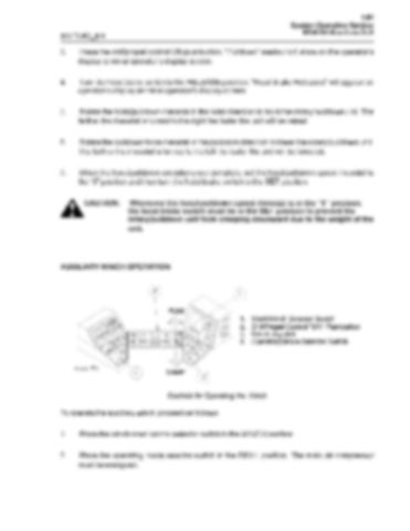
Controls for Operating the Winch
To operate the auxiliary winch proceed as follows: 1.
Place the winch/mast control selector switch in the WINCH position.
2.
Place the operating mode selector switch in the DRILL position. The main air compressor must be energized.

