10 minute read
Breaker shaft only ........................................................ 5


How to remove the breaker shaft assembly only
Whenever performing maintenance procedures, follow all safety regulations and be aware of the following:
WARNING! Before performing maintenance on the machine, the circuit breaker must be in the “OFF” position and the power should be disconnected at the main power source. Electrical shock and accidental machine movement can cause serious injuries or even death to you or the maintenance person.
WARNING! You could be seriously injured or even killed by falling loads. Observe the safe working load limits of lifting or blocking devices and keep a safe distance from suspended loads.
To remove the breaker shaft assembly (Fig. 86).
1. Turn the machine main circuit breaker (CB1) to the “OFF” position.
2. Lock out and tag the power center. Follow standard Federal and mine lockout/tagout procedures.
3. Remove all breaker shaft and gear reducer covers.
4. Remove and cap all grease lines from the breaker shaft.
5. Remove the underspeed sensor from the breaker shaft by loosening the nuts on the u-bolt just enough to allow the senosr to slide out.
6. Properly support the breaker shaft gear reducer so that it does not fall during breaker shaft removal. Ensure that the power unit reaction pin is in place and not removed during this procedured.
7. Attach an appropriate lifting device to the breaker shaft in such a manner that the breaker shaft is level during the lift. Take all slack out of the lifting device in order to support the assembly when mounting hardware is removed.
8. Remove the hardware from the breaker side plates and from between the two halves of the bolt flange and the stub shaft flange.
9. Disengage the pilot fit (1/8 inch) between the stub shaft and bolt flange before attempting to lift the power unit from the machine.
10. Lift the breaker shaft out of the machine.
How to install the breaker shaft assembly
Whenever performing maintenance procedures, follow all safety regulations and be aware of the following:
WARNING! You could be seriously injured or even killed by falling loads. Observe the safe working load limits of lifting or blocking devices and keep a safe distance from suspended loads.
To install the breaker shaft assembly (Fig. 86).
1. Attach an appropriate lifting device to the breaker shaft in such a manner that the breaker shaft is level during the lift and slowly lift the unit onto the machine.
2. Install the one inch hex bolts, hex nuts, and lock washers into the breaker side plates. Torque to 545 ft-lbs.
3. Install the one inch socket head shoulder bolts, 3/4 inch lock washers, and 3/4 inch hex nuts to attach breaker shaft bolt flange to stub shaft in gear reducer. Torque to 240 ft-lbs.
4. Remove support from under gear reducer.
5. Remove lifting device from breaker shaft.
6. Remove caps and install all grease lines to the breaker shaft.
7. Install all breaker shaft and power unit covers.
8. Turn the machine circuit breaker on.
9. Unlock and remove tags from electric power at the power center.
How to disassemble the breaker power unit
To disassemble the breaker power unit proceed as follows (Fig. 86):
WARNING! You could be seriously injured or even killed by falling loads. Observe the safe working load limits of lifting or blocking devices and keep a safe distance from suspended loads.
WARNING! Follow all applicable rules and regulations regarding lockout/ tagout procedures.
IMPORTANT! Caterpillar does not recommend field disassembly or repair of the breaker shaft. If the breaker shaft requires repair, please consult your service representative.
1. Remove complete unit from machine. (See Breaker shaft and breaker power unit removal/installation procedure in this section.)
2. Remove the reducer end cover, bolts, and lock washers.
3. Remove the stub shaft retaining bolt and lock washer.
4. Remove the stub shaft and key from the gear reducer. Note: A jacking screw may be needed to push the stub shaft out of the reducer.
5. Open the access door on the small connecting tube.
6. Loosen the two socket head cap screws that retain the pump coupling half.
7. Attach a lifting device to the pump assembly and take up any slack so that the weight of the pump assembly is resting on the lift device.
8. Remove the four 5/8X2 hex head bolts, 5/8 lock washers, and 5/8 flat washers that retain the pump assembly and remove the pump assembly and the pump coupling half.
9. Attach a lifting device to the small connecting tube.
10. Remove the eight 5/8X2-1/4 hex bolts, 5/8lock washers, and 5/8 flat washers that retain the small connecting tube.
11. Loosen the socket set screw on the motor coupling half and remove from the motor shaft.
12. Attach a lifting eye and lifting device to the electric motor. Take up any slack in the lifting device.
13. Open the access door on the large connecting tube.
14. Remove the eight M12X1.75X35 socket head cap screws and lock washers that attach the flexible coupling to the torque limiter. ________________________________________________________________
15. Remove the eight 3/4X2-1/4 hex bolts, lock washers, and flat washers that retain the electric motor to the connecting tube.
16. Remove the electric motor and flexible coupling sub-assembly.
17. Loosen the three 1/2-13X1-1/2 socket head cap screws on the motor taper loc bushing and remove the flexible coupling and the taper loc bushing using a dead blow hammer.
18. Remove the 1/2X-1/2 hex head cap screw, 1/2 lock washer, and end cap from the electric motor shaft and remove the electric motor key, if necessary.
19. Block under the torque limiter and remove the twelve 7/16-20 socket head cap screws and twelve 7/16 lock washers that retain the torque limiter to the companion flange.
20. Remove the eight M12X1.75X35 socket head cap screws and M12 lock washers that secure the torque limiter to the flex coupling and remove the torque limiter.
21. Loosen the three 1/2-13X1-1/2 socket head cap screws on the reducer taper loc bushing and remove the companion flange and the taper lock bushing sub-assembly from the reducer input shaft using a dead blow hammer.
22. Remove the reducer fan by loosening the set screw in the fan hub.
23. Remove the reducer input shaft seal grease line from the input shaft and the grease manifold.
24. Remove the M16 hex head cap screw, M16 lock washer, and end cap from the gear reducer input shaft.
25. Remove the key from the gear reducer input shaft.
26. Attach a lifting device to the large connecting tube.
27. Remove the four 1X5 hex head bolts and 1 inch lock washers that retain the large connecting tube to the reducer.
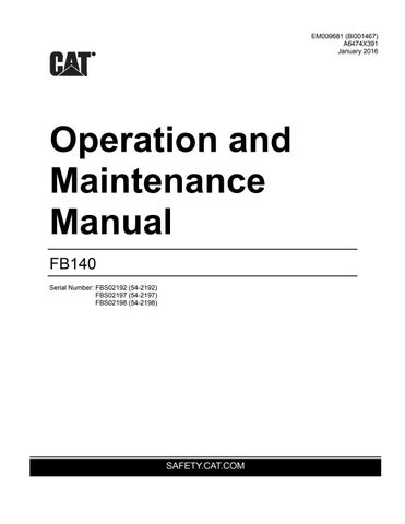
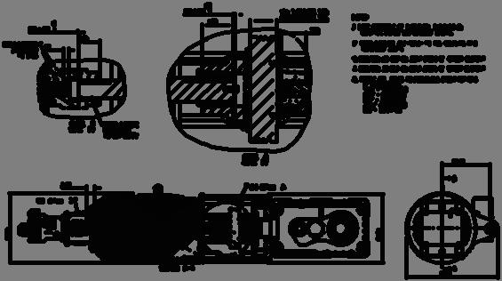
Fig. 86: Breaker power unit assembly

3

1. End cover 2. Stub shaft retaining bolt, M24X65 3. Stub shaft 2
1
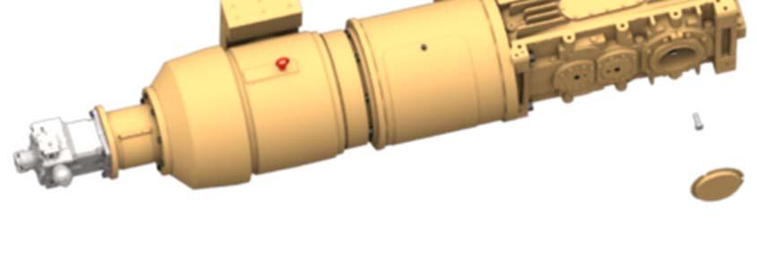
Fig. 86, continued: Breaker power unit assembly
33

1 5 6 7 8
2 3 4
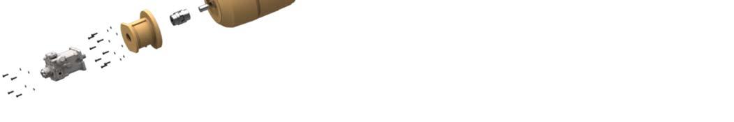
1. Pump 2. Hex head bolt, 5/8X2 (4) 3. Lock washer, 5/8 (4) 4. Connecting tube, small 5. Hex head bolt, 5/8X2-1/4 (8) 6. Lock washer, 5/8 (8) 7. Coupling 8. Motor 9. End cap 10. Lock washer 11. Hex head bolt, 1/2X1-1/2 12. Hex head bolt, 3/4X2-1/4 (8) 13. Lock spring washer, 3/4 (8) 14. Cover, connecting tube 15. Connecting tube, large 16. Flat washer, 1/2 (2) 17. Lock washer, 1/2 (2) 18. Hex head bolt, 1/2X1 (2) 9,10,11
15 19 21,22
20 24 25 28,29
23 26 27
16,17,18 30,31,32 34 35
12,13 14
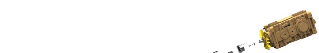
19. Socket head bolt, 1/2-13X1-1/2 (3) 20. Bushing 21. Socket head bolt, M12X1.75X35 (8) 22. Lock washer, M12 (8) 23. Flexible coupling 24. Torque limiter 25. Socket head bolt, 1/2-13X1-1/2 (3) 26. Bushing 27. Companion flange 28. Lock washer, 7/16 (12) 29. Socket head cap screw, 7/16-20X1-1/4 (12) 30. Hex head bolt, M16X2X40 31. Lock washer, M16 32. End cap 33. Gear reducer 34. Lock washer, 1” (4) 35. Hex head cap screw, 1X5 (4)
Fig. 86, continued: Breaker power unit assembly
How to assemble the breaker power unit
To assemble the breaker power unit proceed as follows (Fig. 86):
WARNING! You could be seriously injured or even killed by falling loads. Observe the safe working load limits of lifting or blocking devices and keep a safe distance from suspended loads.
1. Attach a lifting device to the large connecting tube and position on the gear reducer.
2. Attach the large connecting tube to the gear reducer with four 1X5 hex head cap screws and four one inch lock washers. Torque to 900 ft-lb.
3. Attach input shaft seal grease hard line to the input shaft seal housing and the grease manifold.
4. Install the key in the keyway of the gear reducer input shaft.
5. Install the end cap, M16 lock washer, and M16X2X40 hex head bolt to retain the key.
6. Install the reducer fan and secure by tightening the set screw.
7. Install the taper loc bushing and companion flange onto the input shaft of the gear reducer (see Fig. 85 for correct position). Apply
Loctite 242 to the three 1/2-13X1-1/2 socket head cap screws and install to secure the bushing. Torque to 90 ft-lb.
8. Install the torque limiter on the companion flange. Apply Loctite 242 to the 7/16-20 socket head cap screws and tighten to secure the torque limiter.
9. Install the key in the keyway of the electric motor shaft.
10. Install end cap, 1/2 lock washer, and 1/2X1-1/2 hex head bolt into the electric motor shaft to retain the motor shaft key.
11. Install the taper loc bushing and flex coupling on to the electric motor shaft. Do not tighten cap screws.
12. Attach an appropriate lifting device to the electric motor and slowly position the electric motor shaft (with flex coupling and taper loc bushing installed) inside the large connecting tube. Secure with eight 3/4 lock spring washer and eight 3/4X2-1/4 hex head bolts.
Torque to 379 ft-lb.
13. Align the flex coupling with the torque limiter. Apply Loctite 242 to the eight M12X1.75X35 socket head bolts and install the bolts and eight M12 lock washers. Torque to 90 ft-lb.
14. Adjust the electric motor side of the flex coupling assembly and taper loc bushing until proper clearance between the flex coupling jaws is achieved.
15. Remove the three 1/2-13X1-1/2 socket head cap screws, apply
Loctite 242, and reinstall. Torque to 90 ft-lbs.
16. Replace the large connecting tube access cover and secure.
17. Verify that the electric motor shaft key is installed and is retained, if applicable, with end cap and bolt. Install the pump coupling onto the electric motor shaft (see Fig. 85 for correct coupling position).
Apply Loctite 242 to the set screw and tighten to secure the coupling.
18. Install the small connecting tube onto the electric motor and secure with eight 5/8 lock washer and eight 5/8X2-1/4 hex head cap screws. Torque to 210 ft-lb.
19. Remove the bolt from and open the door of the small connecting tube.
20. Attach a lifting device to the pump and orient as shown in Fig. 85.
21. Guide the pump shaft inside the small connecting tube and align the splined shaft with the pump coupling. Secure with four 5/8 lock washers and four 5/8X2 hex head cap screws. Torque to 210 ft-lb.
22. Verify the jaw spacing of the pump coupling (see Fig. 85). Adjust as required by loosening the set screw on the electric motor shaft side and reposition. Once correct position is achieved, tighten set screw.
23. Apply Loctite 242 to the threads of the pump coupling socket head cap screws on the pump side hub. Install cap screws and tighten.
24. Install the key into the keyway of the stub shaft.
25. Apply Never Seeze to the outside diameter of the stub shaft and the key and install into the hollow bore of the gear reducer.
26. Install the stub shaft M24X65 retaining bolt and M24 lock washer and torque bolt to 1,000 ft-lb.
27. Install reducer output shaft end cap and retaining hardware.