2 minute read
Tailpiece installation ..................................................... 5


Installing the tailpiece
To install the tailpiece on the feeder breaker (Reference Fig. 89: Tailpiece installation):
WARNING! You could be seriously injured or even killed by falling loads. Observe the safe working load limits of lifting or blocking devices and keep a safe distance from suspended loads.
1. Install spacer blocks into the underside of the tailpiece weldment.
a. Make sure that bolts will pass through the bearing spacers and the tailpiece weldment. b. Tack weld bearing spacer blocks to tailpiece weldment.
2. Install belt pulley assembly using hex bolts, flat washers, hex nuts, and lock washers.
3. Bolt impact bed assembly to tailpiece weldment using flat washers, lock washers, hex nuts, and bolts.
4. Install slider assembly using flat washers, lock washers, hex nuts, and bolts.
5. Install knuckle piece to tailpiece weldment using tailpiece swivel pin, flat washer, hex nut, keeper pin, and cotter pin.
6. Tighten the hex nut onto the tailpiece swivel pin then weld the pin keeper across the flat of the tailpiece swivel pin on three sides.
7. Position the assembled knuckle joint and the tailpiece frames to the main frame. (Reference figure 86 for placement). Install pins.
8. Install the tailpiece hopper weldments on the main frame using flat washers, lock washers, hex nuts and bolts and flat washers, lock washers, hex nuts, and bolts.
9. Install tailpiece tilt cylinders into the tailpiece hopper weldments and the tailpiece weldment using the swivel clevis weldments, pins, and cotter pins.
10. Install the steering cylinders between the tailpiece frame and the knuckle joint weldment using pins and cotter pins.
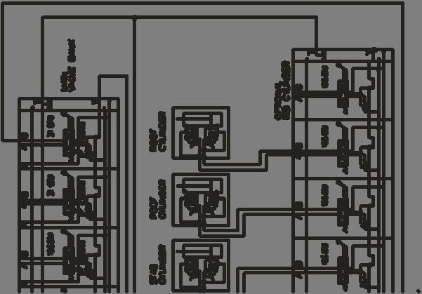
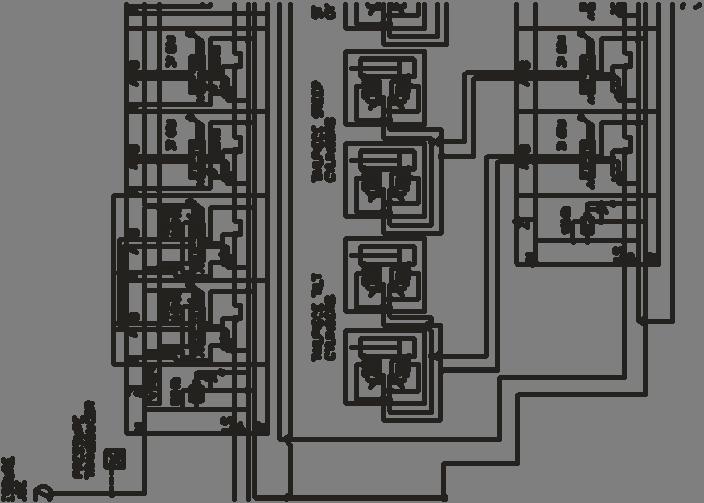
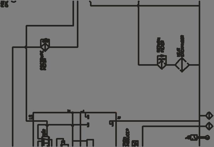
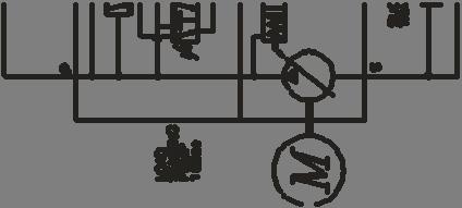
11. Refer to the hydraulic schematic (Fig. 90) for hydraulic installation of the cylinders. Route all hoses, avoiding pinch points, so that hose damage does not occur.
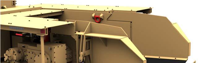
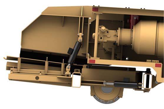
Fig. 89: Tailpiece installation
Valve bank
Tilt cylinder Tailpiece hopper (2)
Tailpiece skirt
Rubber skirt
Impact bed assembly
Steering cylinder
Belt pulley assembly

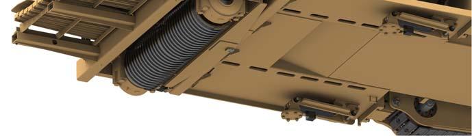
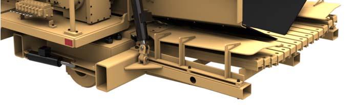
Fig. 89: Tailpiece installation (continued)
Slider saddle assembly Knuckle clevis
Swivel pin
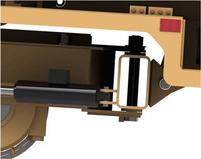
Tailpiece mount clevis
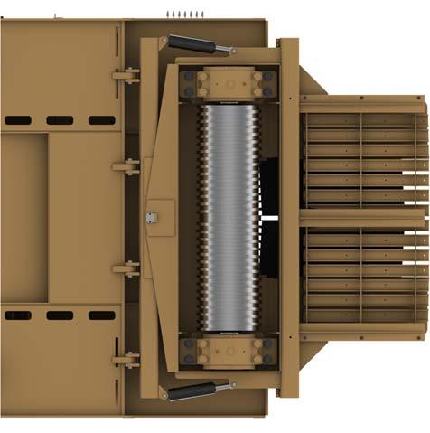
Fig. 90: Tailpiece and Roof Support hydraulic schematic