5 minute read
Breaker shaft and breaker power unit ......................... 5


Breaker shaft and breaker power unit
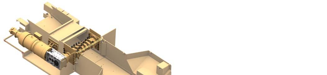
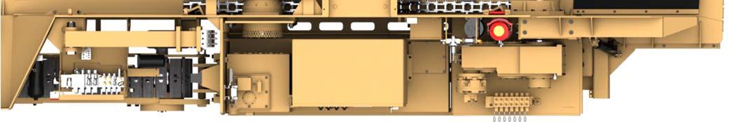
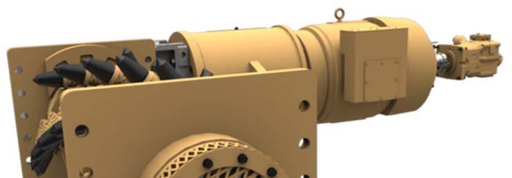
The breaker power unit (Fig. 82) and the breaker shaft assembly (Fig. 83) can be removed or installed as a single assembly or as two separate assemblies.
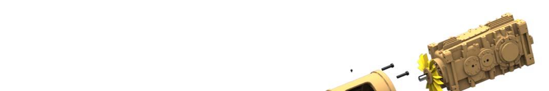
Fig. 82: Breaker power unit main components
1 2 4
3 6
5 7 8 9 10
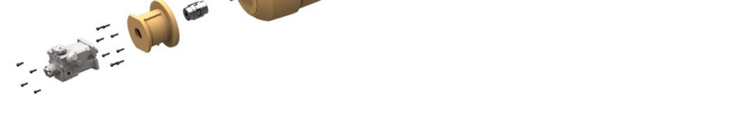

1. Pump assembly 2. Connecting tube 3. Pump coupling 4. Electric motor, 200 hp 5. Flexible coupling 6. Torque limiter clutch 7. Taperloc bushing 8. Companion flange 9. Connecting tube 10. Gear reducer
It is important to check the torque limiter clutch (item 3) for wear. See the Maintenance section of this chapter for the wear check procedure.
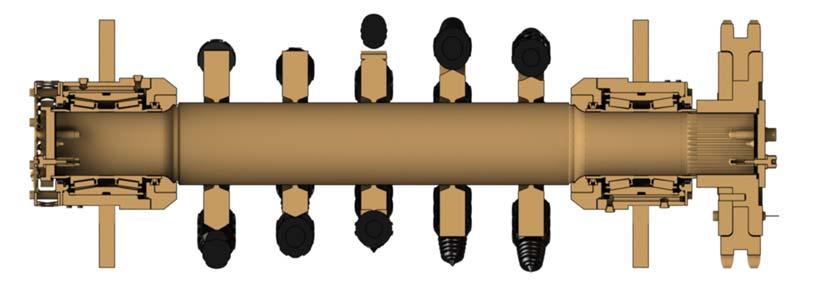
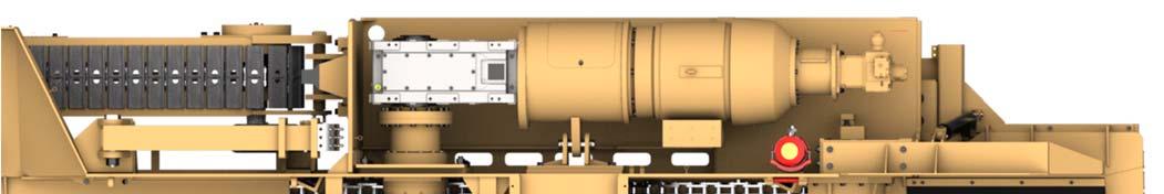
Fig. 83: Breaker shaft assembly
1

2
1. Breaker shaft assembly 2. Breaker power unit assembly

How to remove the breaker shaft and breaker power unit
Whenever performing maintenance procedures, follow all safety regulations and be aware of the following:
WARNING! Before performing maintenance on the machine, the circuit breaker must be in the “OFF” position and the power should be disconnected at the main power source. Electrical shock and accidental machine movement can cause serious injuries or even death to you or the maintenance person.
WARNING! You could be seriously injured or even killed by falling loads. Observe the safe working load limits of lifting or blocking devices and keep a safe distance from suspended loads.
To remove the breaker shaft and breaker power unit as a single assembly (Fig. 84).
1. Turn the machine main circuit breaker (CB1) to the “OFF” position.
2. Lock out and tag the power center. Follow standard Federal and mine lockout/tagout procedures.
3. Remove all power unit and breaker shaft covers.
4. Remove the junction box access panel of the electric motor. Tag and disconnect the cable leads from the motor leads.
5. Remove and cap all grease lines from the breaker shaft, gear reducer, and electric motor.
6. Remove the power unit support structure.
7. Remove the under speed sensor by loosening the nuts on the ubolt and sliding the sensor out.
8. Attach an appropriate lifting device to the breaker shaft and power unit assembly in such a manner to keep breaker shaft and power unit level during the lift. Take all slack out of the lifting device in order to support the assembly when mounting hardward is removed.
9. Remove the hardware from the breaker side plates and the power unit reaction pin.
10. Lift the breaker shaft and power unit out of the machine as an assembly.
How to install the breaker shaft and breaker power unit
Whenever performing maintenance procedures, follow all safety regulations and be aware of the following:
WARNING! You could be seriously injured or even killed by falling loads. Observe the safe working load limits of lifting or blocking devices and keep a safe distance from suspended loads.
To install the breaker shaft and breaker power unit as a single assembly (Fig. 84).
1. Attach an appropriate lifting device in such a manner as to keep the breaker shaft and power unit level during the lift and slowly lift the unit onto the machine.
2. Install the power unit reaction pin and the hardware into the breaker side plates.
3. Install the under speed sensor on the left hand side of the breaker shaft. The distance from the sensor end to end cap target is approximately 1/8 to 1/4 inch.
4. Remove caps and install all grease lines to the breaker shaft, gear box, and electric motor.
5. Reconnect the cable leads to motor leads and install junction box cover. Follow all MSHA, State, and Federal laws.
6. Install the power unit cover support structure.
7. Install all power unit covers.
8. Turn the machine circuit breaker on.
9. Unlock and remove tags from electric power at the power center.
10. Check for proper breaker shaft rotation direction. It may be necessary to switch the breaker motor leads if the shaft is turning in the wrong direction.
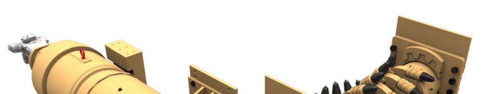
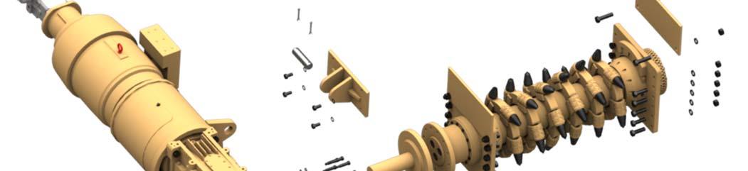
Fig. 84: Breaker shaft and power unit removal and installation
9

11 10
8 1 15 17 18
3
19 12

7 6 5 4 2 16
1. Breaker assembly 2. Stub shaft 3. Breaker power unit assembly 4. Socket head shoulder bolt, 1X3 (12) 5. Lock washer, 3/4 (12) 6. Hex nut, 3/4 (12) 7. Hex head bolt, M24x65-10.9 8. Pivot lug 9. Power unit reaction pin 10. Pivot lug mounting plate 11. Lock washer, 1” (4) 12. Hex head bolt, 1X2 (4) 13. Underspeed sensor mount (shown on next page) 14. U-bolt, 2X3-3/4X3/8-16 (shown on next page) 15. Hex head bolt, 1-1/4X5 (4) 16. Hex head bolt, 1-1/4X4 (20) 17. Lock washer, 1-1/4 (24) 18. Hex nut, 1-1/4 (24) 19. Reducer end cover (reference only)
Fig. 84, continued: Breaker shaft and power unit removal and installation
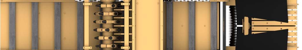

14
13