2 minute read
Conveyor drive unit ...................................................... 5


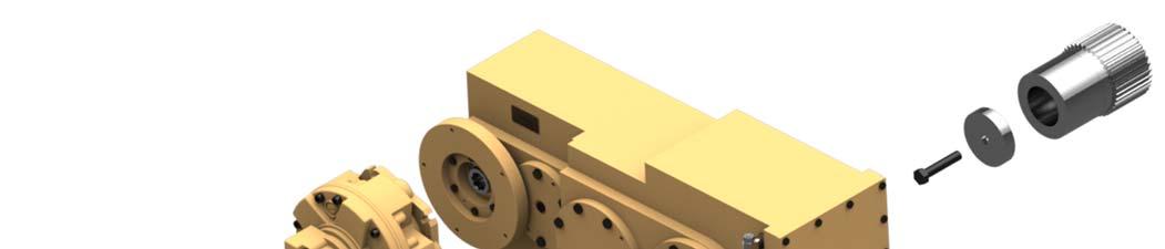
Fig. 87: Conveyor drive unit
5
4
Conveyor drive unit
The conveyor drive unit (Fig. 87) has been assembled as a unit and can be removed and installed as a unit.
7
6
2 3
8
1

1. Hex head bolt, 2. Lockwasher, 3. Flat washer, 4. Hydraulic motor 5. Gearbox 6. Headshaft retainer 7. Headshaft splined adapter 8. Hex head bolt 9. End cap 9
How to remove the conveyor drive unit (Fig. 87)
Whenever performing maintenance procedures, follow all safety regulations and be aware of the following:
WARNING! Before performing maintenance on the machine, the circuit breaker must be in the “OFF” position and the power should be disconnected at the main power source. Electrical shock and accidental machine movement can cause serious injuries or even death to you or the maintenance person.
WARNING! You could be seriously injured or even killed by falling loads. Observe the safe working load limits of lifting or devices and keep a safe distance from suspended loads.
1. Remove the last cover on the left hand side of the machine.
2. Remove the last cover’s support post.
3. Remove the hydraulic motor:
a. Disconnect, tag, and cap all hydraulic hoses to the motor.
b. Attach an appropriate lifting device to the motor and take up all slack so that the weight of the motor is resting on the lifting device.
c. Remove the five (5) 1/2 inch bolts, lock washers, and flat washers from the end of the motor.
4. Remove the conveyor gear reducer:
a. Insert a lifting lug into the threaded hole on top of the gear reducer and attach an appropriate lifting device to the lug.
Take up all slack so that the weight of the gear reducer is resting on the lifting device.
b. Remove the four (4) bolts from the end cap on the output stage of the reducer.
c. Insert two (2) of the bolts in the threaded pusher holes to remove the cover.
d. Remove the retaining bolt.
e. Remove the retainer end cap.
f. Remove the cotter pin and retainer pin from the clevis on the front of the reducer.
g. Using the lifting device, slide the gear reducer off of the head shaft.
h. Remove the splined adapter from the head shaft.
How to install the conveyor drive unit (Fig. 87)
1. Install the hydraulic motor onto the input shaft of the gear reducer:
a. Attach an appropriate lifting device to the motor and position the motor on the gear reducer.
b. Install the five (5) 1/2 inch mouting bolts, lock washers, and flat washers and torque to 400 ft-lbs.
c. Reconnect hydraulic hoses.
2. Install the conveyor gear reducer:
a. Attach an appropriate lifting device to the lifting lug located on top of the reducer and position the reducer on the head shaft.
b. Insert the retainer end cap and secure with the M20X2.5X100
Grade 10.9 retaining bolt. Torque the bolt to 450 ft-lbs.
c. Insert the reaction pin and secure with 1/4 inch cotter pin.
d. Place the end cap on the output stage of the reducer and secure with four (4) bolts.
3. Install the last cover’s support post.
4. Install the last cover on the left hand side of the machine.