3 minute read
Breaker power unit only ................................................ 5


How to remove the breaker power unit assembly
Whenever performing maintenance procedures, follow all safety regulations and be aware of the following:
WARNING! Before performing maintenance on the machine, the circuit breaker must be in the “OFF” position and the power should be disconnected at the main power source. Electrical shock and accidental machine movement can cause serious injuries or even death to you or the maintenance person.
WARNING! You could be seriously injured or even killed by falling loads. Observe the safe working load limits of lifting or blocking devices and keep a safe distance from suspended loads.
To remove the breaker power unit proceed as follows (Fig. 84).
1. Turn the machine main circuit breaker (CB1) to the “OFF” position.
2. Lock out and tag the power center. Follow standard Federal and mine lockout/tagout procedures.
3. Remove all power unit covers.
4. Remove the junction box access panel of the electric motor. Tag and disconnect the cable leads from the motor leads.
5. Remove and cap all grease lines from the gear reducer and electric motor.
6. Remove the under speed sensor.
7. Attach an appropriate lifting device to the power unit assembly in such a manner as to keep the power unit level during the lift. Take all slack out of the lifting device in order to support the assembly when mounting power unit reaction pin and bolts from breakershaft bolt flange and stub shaft are removed.
8. Remove the twelve (12) one inch socket head sholder bolts, twelve (12) 3/4 inch lock washers, and twelve (12) 3/4 inch hex nuts that connect the breaker shaft bolt flange to the stub shaft.
9. Remove cotter pins from the power unit reaction pin and remove the pin.
10. Disengage the pilot fit (1/8 inch) between the stub shaft and bolt flange before attempting to lift the power unit from the machine.
11. Lift the power unit out of the machine.
How to install the breaker power unit assembly
To install the breaker power unit proceed as follows (Fig. 84).
Whenever performing maintenance procedures, follow all safety regulations and be aware of the following:
WARNING! You could be seriously injured or even killed by falling loads. Observe the safe working load limits of lifting or blocking devices and keep a safe distance from suspended loads.
1. Attach an appropriate lifting device to the power unit in such a manner that the power unit is level during the lift and slowly lift the unit onto the machine.
2. Install the power unit reaction pin and secure with cotter pins.
3. Bolt the breaker shaft bolt flange to the stub shaft.
4. Remove the lifting device.
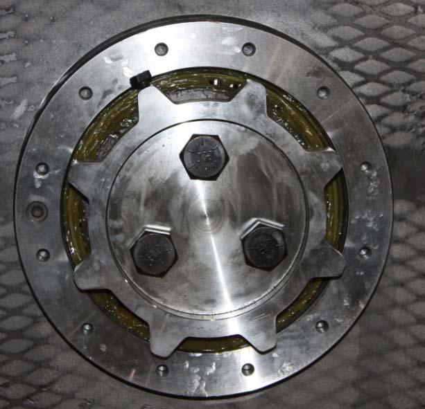
5. Install the under speed sensor on the breaker shaft. Distance
from sensor end to end cap target is approximately
1/8” to 1/4”. Note (Reference Fig. 85): The end cap is gear shaped with eight “teeth”. The teeth are targets for the underspeed sensor.
Fig. 85: Sensor target
6. Remove caps and install all grease lines to the gear box and electric motor.
7. Reconnect the cable leads to motor leads and install junction box cover. Follow all MSHA, State, and Federal laws.
8. Install all power unit covers.
9. Unlock and remove tags from electric power at the power center.
10. Turn the machine circuit breaker on.
11. Check for proper breaker shaft rotation direction. It may be necessary to switch the breaker motor leads if the shaft is turning in the wrong direction.