t
t
BI005074
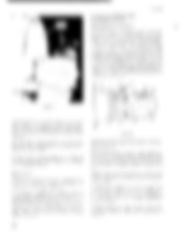
AUXILIARY HOISTS AND OVERHEAD CRANE Adjustment of Load Brake The multiple discs of the brake work at about onefourth the pressure of the surface screw type brakes; therefore, adjustment is seldom required. If adjustment becomes necessary, lower the block to the £1001', loosen lock nut C and tighten adjusting screw F with about a six-inch wrench until mod~rate resistance is felt (figure 60). Back out the adjusting screw one-half turn and tighten lock nut C. Check the adjustment by removing air vent plug A and observing the movement of the compound internal gear when approximately full load is lifted from the £1oor. This movement should be about three-eighths inch. A
c
F
FIGURE 59
locked to the shaft. Certain bearings use set screws; tighten them. Some bearings use an eccentric locking collar which should be driven on in the direction of fan rotation and then held in position with set screws. Turn the wheel over by hand to make sure it runs free and clear. Reposition by shifting and or shimming, if necessary. Be sure all anchor bolts, bearings, motor bolts and set screws are tight. Make certain the bearings ha ve am ple pIe lu brica tion.
Maintenance Maintenance, basically, consists of applying proper lubricants in bearings. Check lubrication once each week under normal conditions. It is preferable to add grease while the shaft is slowly turned. Add grease until it starts to ooze through the bearing seals. Wipe excess grease off. Exercise care when lubricating with a highpressure type gun or the bearing seals may be ruined. The bearing should run warm after being filled with grease.
52
FIGURE 60
Adjustment of Clapper Type Electric Brake Refer to figure fiO. Braking power may be varied by moving the fulcrum Y. No.1 position gives maximum power, No. () position minimum power. The factory setting is shown on the nameplate attached to the brake case. Adjust bridge and trolley brakes as desired; hoist brakes should never be reduced in power from the factory setting. As the friction surfaces wear, the air gap G will increase. The air gap should never be allowed to exceed the maximum shown on the nameplate. It is preferable to keep the air gap considerably below maximum. To reduce the air gap, remove the pin and turn the rocl counterclockwise until the minimum air gap is restored.


