8 minute read
Brakes - Style 2


2
B-MAX. B-MAX. BRAKE BRAKE SET-NEW SET-NEW LININGS LININGS B-MIN. B-MIN. BRAKE BRAKE SET-REPLACE SET-REPLACE LININGS LININGS
3 3
1. 1. SHIMS SHIMS OR OR SPACERS SPACERS (IF (IF REQUIRED) REQUIRED) 2. 2. BOLT BOLT 3. 3. BRAKE BRAKE SUPPORT SUPPORT
FIGURE FIGURE 41 41
(0/ -._/ / (0/ -._/ /
ADJUSTMENT ADJUSTMENT (figure (figure 4:3) 4:3)
a. a. When When brake brake wears wears and and "A" "A" dimension dimension approaches approaches A-min A-min length, length, the the spring spring rod rod bolts bolts will will have have to to be be adjusted adjusted to to A-max. A-max.
Also, Also, adjust adjust adjusting adjusting bolts bolts on on the the sides sides of of the the brake brake support support to to gain gain equal equal clearance clearance of of 1/16 1/16 inch inch between between drum drum and and lining lining when when brake brake is is released. released.
b. b. After After several several adjustments, adjustments, check check the the disdistance tance between between cylinder cylinder anchor anchor pins, pins, didimension mension "13". "13". When When this this dimension dimension apapproaches proaches B-Min, B-Min, the the linings linings must must be be replaced. replaced.
J 4 4
o
7 8 9 7 8 9 10 10
1. 1. ROD ROD BOLT BOLT 2. 2. ROD ROD BOLT BOLT NUTS NUTS 3. 3. BUSHING BUSHING 4. 4. ASSEMBLY ASSEMBLY PIN PIN 5. 5. SPRING SPRING 6. 6. SPRING SPRING GUIDE GUIDE 7. 7. HOUSING HOUSING 8. 8. NUTS NUTS 9. 9. FOLLOWER FOLLOWER 10. 10. PISTON PISTON CUP CUP 11. 11. PISTON PISTON ASSEMBLY ASSEMBLY
FIGURE FIGURE 42 42 2
"2
1/4" 1/4" CLEARANCE CLEARANCE BRAKE BRAKE RELEASED RELEASED
1. 1. SPRING SPRING ADJUSTING ADJUSTING ROD ROD BOLT BOLT NUTS NUTS 2. 2. ADJUSTING ADJUSTING BOLTS BOLTS
FIGURE FIGURE 43 43
Brake Brake style style 2 2 (figure (figure 44) 44) h h CAUTION: CAUTION: Prior Prior to to working working on on any any .. .. brakes, brakes, observe observe the the following following precauprecautions: tions:
1. 1. Place Place walking walking shoes shoes and and bucket bucket on on ground. ground.
2. 2. De-energize, De-energize, lock lock out out and and tag tag all all controls. controls.
3. 3. Set Set all all brakes brakes except except those those being being worked worked on. on. A A minimum minimum of of one one brake brake per per unit unit should should always always be be set. set.
To To disassemble disassemble style style 2 2 brakes brakes (fig'ure (fig'ure 45) 45) proceed proceed as as follows: follows: 1. 1. }{emove }{emove the the brake brake guard. guard.
2. 2. Remove Remove the the spring spring rod rod bolt boltnut. nut. Back Back off offon on the the rod rod bolt boltspecial special nut nut until until all all tension tension is is removed removed from from the the spring. spring.
;). ;). Unbolt Unboltthe the brake brake support supportbracket bracketand and slide slidethe the complete complete brake brake assembly assembly from from the the brake brake drum. drum.
Note, Note, ifused, ifused, the the thickness thickness and and location location of ofthe the shims shims under under the the bracket, bracket, so so that that when when the the bracket bracket is is remounted, remounted, the the brake brake will will align align properly properly with with the the brake brake drum. drum.
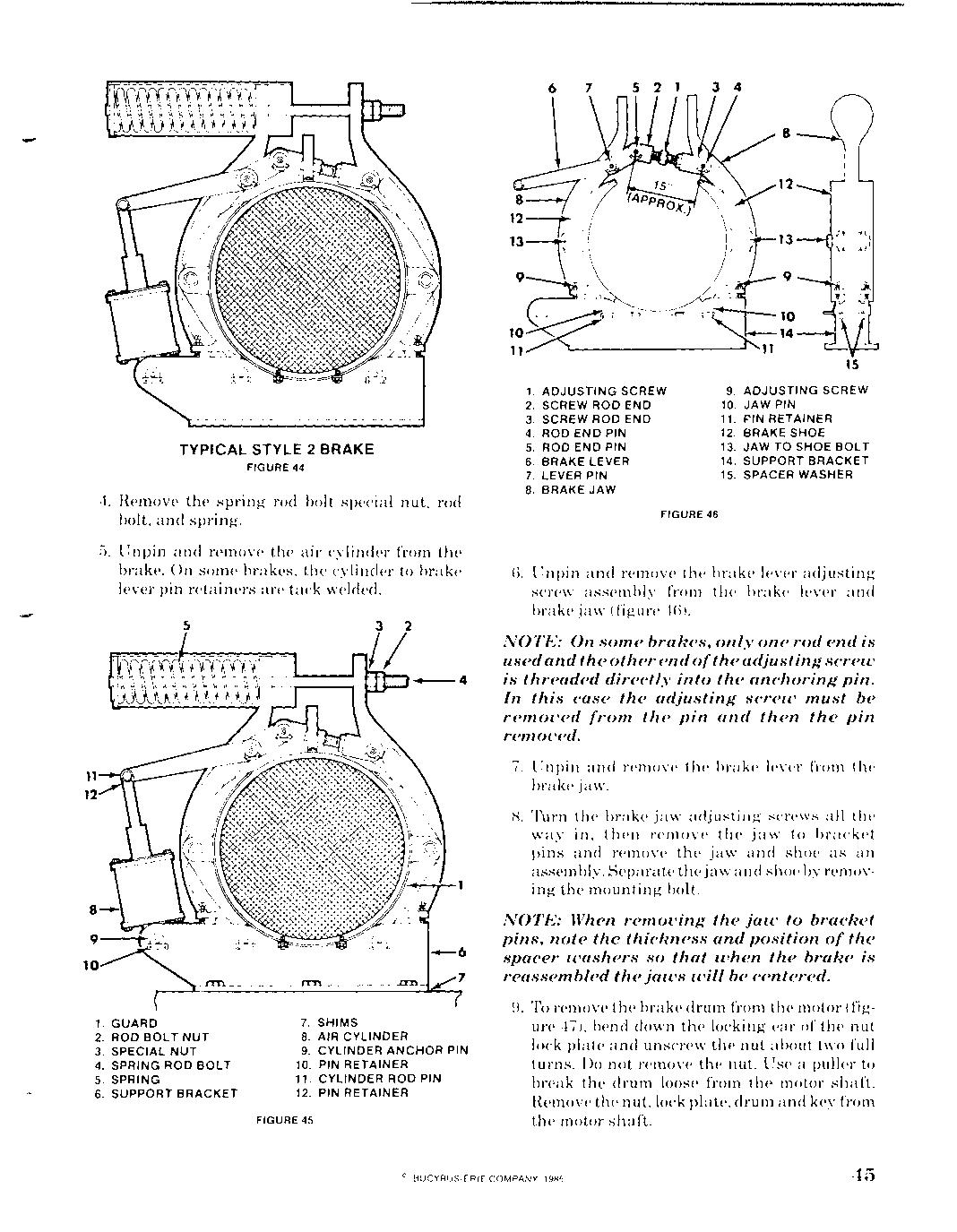
TYPICAL TYPICAL STYLE STYLE 2 2 BRAKE BRAKE
FIGURE FIGURE 44 44
4. 4. Remove Remove the the spring spring rod rod bolt bolt special special nut, nut, rod rod bolt, bolt, and and spring. spring.
5. 5. Unpin Unpin and and remove remove the the air air cylinder cylinder from from the the brake. brake. On On some some brakes, brakes, the the cylinder cylinder to to brake brake lever lever pin pin retainers retainers are are tack tack welded. welded.
5 5
11 11 12 12
1. 1. GUARD GUARD 2. 2. ROD ROD BOLT BOLT NUT NUT 3. 3. SPECIAL SPECIAL NUT NUT 4. 4. SPRING SPRING ROD ROD BOL BOLT T 5. 5. SPRING SPRING 6. 6. SUPPORT SUPPORT BRACKET BRACKET 7. 7. SHIMS SHIMS 8. 8. AIR AIR CYLINDER CYLINDER 9. 9. CYLINDER CYLINDER ANCHOR ANCHOR PIN PIN 10. 10. PIN PIN RETAINER RETAINER 11. 11. CYLINDER CYLINDER ROD ROD PIN PIN 12. 12. PIN PIN RETAINER RETAINER
FIGURE FIGURE 45 45
1. 1. ADJUSTING ADJUSTING SCREW SCREW 2. 2. SCREW SCREW ROD ROD END END 3. 3. SCREW SCREW ROD ROD END END 4. 4. ROD ROD END END PIN PIN 5. 5. ROD ROD END END PIN PIN 6. 6. BRAKE BRAKE LEVER LEVER 7. 7. LEVER LEVER PIN PIN 8. 8. BRAKE BRAKE JAW JAW
,s ,s
9. 9. ADJUSTING ADJUSTING SCREW SCREW 10. 10. JAW JAW PIN PIN 11. 11. PIN PIN RETAINER RETAINER 12. 12. BRAKE BRAKE SHOE SHOE 13. 13. JAW JAW TO TO SHOE SHOE BOLT BOLT 14. 14. SUPPORT SUPPORT BRACKET BRACKET 15. 15. SPACER SPACER WASHER WASHER
FIGURE FIGURE 46 46
G. G. Unpin Unpin and and remove remove the the brake brake lever lever adjusting adjusting screw screw assembly assembly from from the the brake brake lever lever and and brake brake jaw jaw (figure (figure 4GL 4GL
NOTE: NOTE: On On some some brakes, brakes, only only one one rod rod end end is is used usedand and the the other other end end of ofthe the adjusting adjusting screw screw is is threaded threaded directly directly into into the the anchoring anchoring pin. pin. In In this this case case the the adjusting adjusting screw screw must must be be removed removed from from the the pin pin and and then then the the pin pin removed. removed.
7. 7. Unpin Unpin and and remove remove the the brake brake lever lever from from the the brake brake jaw. jaw.
K K Turn Turn the the brake brake jaw jaw adjusting adjusting screws screws all all the the way way in, in, then then remove remove the the ja jaw w to to bracket bracket pins pins and and remove remove the the jaw jaw and and shoe shoe as as an an assembly. assembly. Separate Separate the the jaw jawand and shoe shoe by by removremoving ing the the mounting mounting bolt. bolt.
NOTE: NOTE: When When removing removing the the jaw jaw to to bracket bracket pins, pins, note note the the thickness thickness and and position position of of the the spacer spacer washers washers so so that that when when the the brake brake is is reassembled reassembled the the jaws jaws will will be be centered. centered.
To To remove remove the the brake brake drum drum from from the the motor motor (fig(figure ure 47), 47), bend bend down down the the locking locking ear ear of of the the nut nut lock lock plate plate and and unscrew unscrew the the nut nut about about two two full full turns. turns. Do Do not not remove remove the the nut. nut. Use Use a a puller puller to to break break the the drum drum loose loose from from the the motor motor shaft. shaft. Remove Remove the the nut, nut, lock lock plate, plate, drum drum and and key key from from the the motor motor shaft. shaft.
'4 5
1. BRAKE DRUM 2. DRUM KEY 3. MOTOR MOTOR NUT NUT 4. LOCK PLATE 5. MOTOR
FIGURE 47
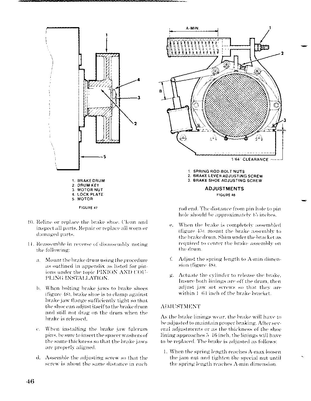
10. l{eline or replace the brake shoe. Clean and inspect all parts. Hepair or replace all worn or damaged parts. the Hepair
11. l{eassemble J{eassemble in in reverse of disassembly noting the following:
a. Mount the the brake drum using the the procedure as outlined in appendix as listed for for pinions under the topic topic PINION AND COU-
PLING INSTALLATION. INSTALLATION.
b. When When bolting brake jaws to brake shoes (figure 48), brake shoe is to clamp against against brake jaw flange flange sufficiently tight so so that the shoe can adjustitself itselfto the the brakedrum and still not drag on the the drum when the the brake is released.
c. When installing the brake jaw fulcrum pins, be sure to insert the spacer washers of the same thickness so that the brake jaws are properly aligned. the that jaws
d. Assemble the adjusting screw so that the screw is about the the same distance in in each each
1. SPRING ROD BOLT NUTS 2. BRAKE LEVER ADJUSTING SCREW 3. BRAKE SHOE ADJUSTING SCREW SCREW
ADJUSTMENTS
FIGURE 48
rod end. The distance from pin pin hole to pin hole should be If) inches. inches.
e. e. When the the brake is completely assembled assembled (figure 45), mount the brake assembly assembly to the brake drum. Shim under the the bracket as required to center the brake assembly on the the drum.
f f Adjust the the spring length to A-min dimension (figure 48).
g. Actuate the cylinder to release the brake.
Insure both linings are off off the drum, drum, then adjust jaw set scre"vs so that they they are within 1/64 1/64 inch of the brake bracket.
AD,JUSTMENT AD,JUSTMENT
As the the brake linings wear, the brake will have to be adjusted adjusted to maintain proper proper braking. After several adjustments or as the thickness of the shoe shoe lining approaches 5/16 inch, the the linings will have to be replaced. The brake is adjusted adjusted as follows:
1. When When the spring length reaches reaches A-max loosen the the jam nut and tighten tighten the special nut nut until until the the spring length reaches A-min dimension.