6 minute read
Brakes - Style 4 and 5 , :)8 Brakes - Style 7


1 1
DISTANCE DISTANCE BETWEEN BETWEEN PIN PIN (ARMS (ARMS CLOSED CLOSED MAXIMUM) MAXIMUM)
1 1
MEASURED MEASURED DISTANCE DISTANCE
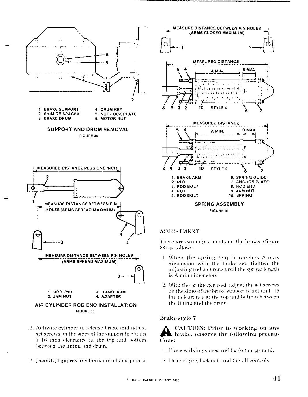
1. 1. BRAKE BRAKE SUPPORT SUPPORT 2. 2. SHIM SHIM OR OR SPACER SPACER 3. 3. BRAKE BRAKE DRUM DRUM 2 2
4. 4. DRUM DRUM KEY KEY 5. 5. NUT NUT LOCK LOCK PLATE PLATE 6. 6. MOTOR MOTOR NUT NUT
SUPPORT SUPPORT AND AND DRUM DRUM REMOVAL REMOVAL
FIGURE FIGURE 34 34 5 4 5 4
MEASURED MEASURED DISTANCE DISTANCE
A MIN. r-------------------<-j A MIN. -----------<-j B MAX. r--J B MAX. r--J
MEASURED MEASURED DISTANCE DISTANCE PLUS PLUS ONE ONE INCH INCH
MEASURE MEASURE DISTANCE DISTANCE BETWEEN BETWEEN PIN PIN HOLES HOLES (ARMS (ARMS SPREAD SPREAD MAXIMUM) MAXIMUM) ,+-__..,., A---f"''''' 89 89
1. 1. BRAKE BRAKE ARM ARM 2. 2. NUT NUT 3. 3. ROO ROO BOLT BOLT 4. 4. NUT NUT 5. 5. ROD ROD BOLT BOLT 6. 6. SPRING SPRING GUIDE GUIDE 7. 7. ANCHOR ANCHOR PLATE PLATE 6. 6. ROD ROD END END 9. 9. JAM JAM NUT NUT 10. 10. SPRING SPRING
SPRING SPRING ASSEMBLY ASSEMBLY
FIGURE FIGURE 36 36
1-"--3
MEASURE MEASURE DISTANCE DISTANCE BETWEEN BETWEEN PIN PIN HOLES HOLES (ARMS (ARMS SPREAD SPREAD MAXIMUM) MAXIMUM)
3 3
1. 1. ROD ROD END END 2. 2. JAM JAM NUT NUT 3. 3. BRAKE BRAKE ARM ARM 4. 4. ADAPTER ADAPTER
AIR AIR CYLINDER CYLINDER ROD ROD END END INSTALLATION INSTALLATION
FIGURE FIGURE 35 35
12. 12. Activate Activate cylinder cylinder to to release release brake brake and and adjust adjust set set screws screws on on the the sides sides of ofthe the support support to to obtain obtain 1/16 1/16 inch inch clearance clearance at at the the top top and and bottom bottom between between the the lining lining and and drum. drum.
1 1:3. :3. Install Installall all guards guards and and lubricate lubricate all all lube lube points. points. There There are are two two adjustments adjustments on on the the brakes brakes (figure (figure :l8) :l8) as as follows: follows:
1. 1. When When the the spring spring length length reaches reaches A-max A-max dimension dimension with with the the brake brake set, set, tighten tighten the the adjusting adjusting rod rod bolt bolt nuts nuts until until the the spring spring length length is is A-min A-min dimension. dimension.
2. 2. With With the the brake brake released, released, adjust adjust the the set set screws screws on on the the sides sides of ofthe the brake brake support supportto to obtain obtain 1 1 16 16 inch inch clearance clearance at at the the top top and and bottom bottom between between the the lining lining and and the the drum. drum.
Brake Brake style style 7 7 h. h. CAUTION: CAUTION: Prior Prior to to working working on on any any .. .. brake, brake, observe observe the the following following precauprecautions: tions:
1. 1. Place Place walking walking shoes shoes and and bucket bucket on on ground. ground.
2. 2. De-energize, De-energize, lock lock out, out, and and tag tag all all controls. controls.
REMOVE NUTS AND VERIFY A MIN. AND B MAX. DIMENSIONS B MAX. \
STYLE STYLE 4 4
SPRING SPRING ADJUSTMENT ADJUSTMENT
FIGURE 37 STYLE STYLE 5 5
:3. Set all brakes, except those being worked on. A minimum ofone brake per unit should always be set. one
Disassemble style 7 brake (figure :39) as as follows:
1. Remove all guards.
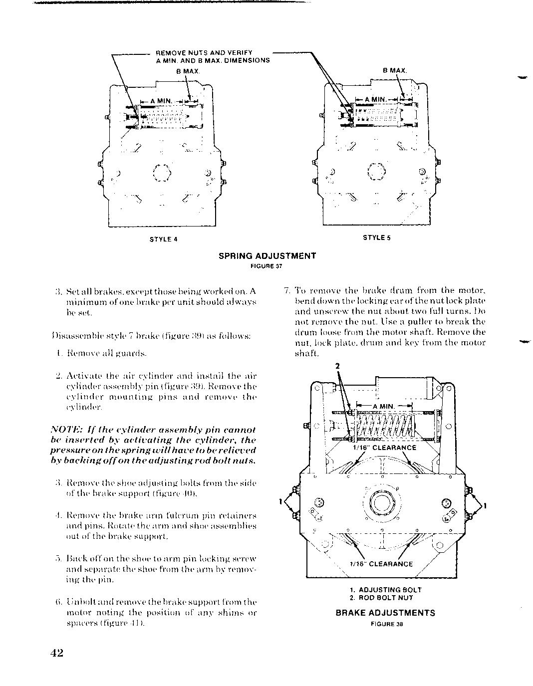
2. Activate the air cylinder and instaH the air cylinder assembly pin (figure :39). Remove the cylinder mounting pins and remove the cylinder. the and the
NOTE: If the the cylinder assembly pin cannot be inserted by activating the cylinder, the pressure on the the spring will have to be relieved by backing offon the adjusting rod bolt nuts.
:3. Remove the shoe adjusting bolts bolts from the side of the brake support (figure 40).
4. Remove the brake arm fulcrum pin retainers and pins. the the arm arm and shoe assemblies out of the brake brake support.
c). Back off on the shoe to arm pin locking screw and separate the shoe from the arm by removing the pin. pin the
6. 6. Unbolt and remove the brake support from the the motor noting the the position of any shims or spacers (figure 41). 7. To remove the brake drum from the motor, bend down the locking ear ofthenut lock plate and unscrew the nut about two full turns. Do not remove the nut. Use a puller to break the drum loose from the motor shaft. Remove the nut, lock plate, drum and key from the motor shaft. the ear nut nut turns. the from Remove lock shaft.
2
1
1/16" CLEARANCE CLEARANCE
1. 1. ADJUSTING ADJUSTING BOLT BOLT
2. ROD ROD BOLT BOLT NUT NUT
BRAKE ADJUSTMENTS
FIGURE 38
TYPICAL TYPICAL STYLE STYLE 7 7 BRAKE BRAKE
FIGURE FIGURE 39 39
8. 8. To To separate separate air air cylinder cylinder assembly assembly (figure (figure 42), 42), back back off off on on the the spring spring adjusting adjusting rod rod bolt bolt nuts nuts until until all all tension tension is is removed removed from from the the spring, spring, then then remove remove the the nuts, nuts, spring spring retainer, retainer, rod rod bolts bolts and and spring. spring. Remove Remove the the cylinder cylinder assemassembly bly pin pin and and slide slide the the piston piston from from the the cylinder. cylinder.
Remove Remove the the nuts nuts from from the the end end of ofthe the piston piston rod rod and and remove remove the the follower follower and and piston piston cup. cup.
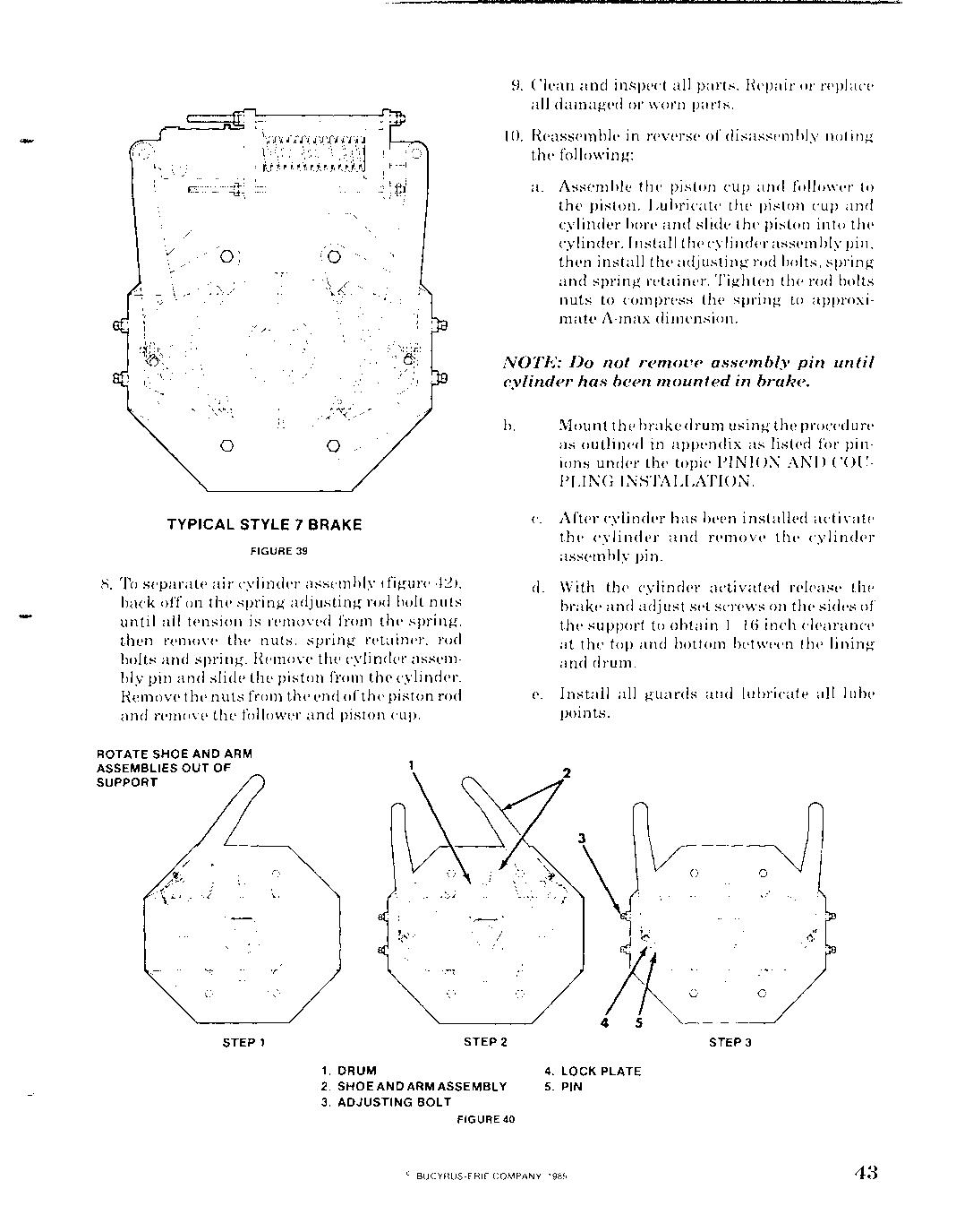
ROTATE ROTATE SHOE SHOE AND AND ARM ARM ASSEMBLIES ASSEMBLIES OUT OUT OF OF SUPPORT SUPPORT
9. 9. Clean Clean and and inspect inspect all all parts. parts. Hepair Hepair or or replace replace all all damaged damaged or or worn worn parts. parts.
10. 10. Reassemble Reassemble in in reverse reverse of of disassembly disassembly noting noting the the following: following:
a. a. Assemble Assemble the the piston piston cup cup and and follower follower to to the the piston. piston. Lubricate Lubricate the the piston piston cup cup and and cylinder cylinder bore bore and and slide slide the the piston piston in into to the the cylinder. cylinder. Install Install the thecylinder cylinderassembly assembly pin, pin, then then install install the the adjusting adjusting rod rod bolts, bolts, spring spring and and spring spring retainer. retainer. Tigh Tighten ten the the rod rod bolts bolts nuts nuts to to compress compress the the spring spring to to approxiapproximate mate A-max A-max dimension. dimension.
NOTE: NOTE: Do Do not not remove remove assembly assembly pin pin until until cylinder cylinder has has been been mounted mounted in in brake. brake.
b. b. Mount Mount the the brake brakedrum drum using using the the procedure procedure as as outlined outlined in in appendix appendix as as listed listed for for pinpinions ions under under the the topic topic PINION PINION AND AND COUCOUPLING PLING INSTALLATION. INSTALLATION.
c. c. After After cylinder cylinder has has been been installed installed activate activate the the cylinder cylinder and and remove remove the the cylinder cylinder assembly assembly pin. pin.
d. d. With With the the cylinder cylinder activated activated release release the the brake brake and and adjust adjust set set screws screws on on the the sides sides of of the the support support to to obtain obtain 1 1 16 16 inch inch clearance clearance at at the the top top and and bottom bottom between between the the lining lining and and drum. drum.
e. e. Install Install all all guards guards and and lubricate lubricate all all lube lube points. points.
STEP STEP 1 1 STEP STEP 2 2
1. 1. DRUM DRUM 2. 2. SHOE SHOE AND AND ARM ARM ASSEMBLY ASSEMBLY 3. 3. ADJUSTING ADJUSTING BOLT BOLT
FIGURE FIGURE 40 40 4 5
4. 4. lOCK lOCK PLATE PLATE 5. 5. PIN PIN