1 minute read
To remove the first reduction gearcase cover


s
3
4--_-11
3/8" FILLET WELD WELD RACK TO BASE
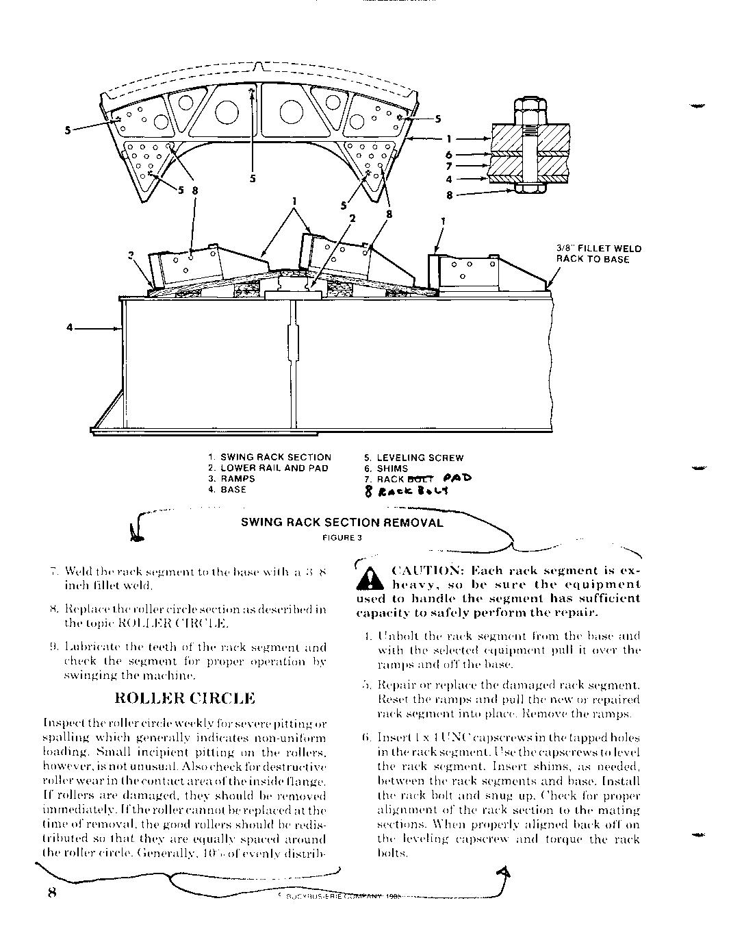
1. SWING RACK SECTION 5. LEVELING SCREW 2. LOWER RAIL AND PAD 6. SHIMS 3. 4. RAMPS BASE 7. 8 RACK PAT:> I.\,.1
SWING RACK
FIGURE FIGURE 3 3 • • ."" 0"" ..•.. .0. o'
.. -.-----A----"
7. Weld the rack segment to the base with a :VH inch fillet weld.
H. Replace the roller circle section as described in the topic ROLLER CIRCLE.
9. Lubricate the teeth of the rack segment and check the segment for proper operation by swinging the machine.
ROLLER CIRCLE
Inspect the roller circle weekly for severe pitting pitting or spalling which generally indicates non-uniform loading. Small incipient pitting on the rollers, however, is not unusual. Also check for destructive roller wear in in the contact contact area ofthe inside f1ange. If rollers are damaged, they should be removed immediately. Ifthe roller cannot be replaced replaced at the time of removal, removal, the good rollers should be redistributed so so that they are equally spaced around the roller circle. Generally, 101];1 of evenly distribdistribCAUTION: Each rack segment is exheavy, so be sure the equipment equipment used to handle the segment has sufficient capacity to safely perform the repair.
4. Unbolt the rack segment from the base and with the selected equipment pull it over the ramps and off the base. G. Repair or or replace the damaged rack segment.
Reset the ramps and pull the new or repaired rack segment into place. Remove the ramps.
6. Insert 1 x:1 UNC capscrews in the tapped holes in the rack segment. Use the capscrews to level the rack segment. Insert shims, as needed, between the rack segments and base. Install the rack bolt and snug up. Check for proper alignment of the rack section to the mating sections. When properly aligned back off on the leveling capscrew and torque the rack bolts. J the the the torque bolts. 4 ••. ' .--l