BI005074 B-MAX. BRAKE SET-NEW LININGS B-MIN. BRAKE SET-REPLACE LININGS
1
-
2
/
(0/ -._/
3 "2
2
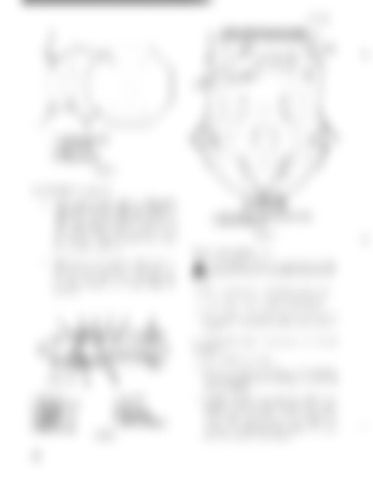
1. SHIMS OR SPACERS (IF REQUIRED) 2. BOLT 3. BRAKE SUPPORT FIGURE 41
ADJUSTMENT (figure 4:3) a.
When brake wears and "A" dimension approaches A-min length, the spring rod bolts will have to be adjusted to A-max. Also, adjust adjusting bolts on the sides of the brake support to gain equal clearance of 1/16 inch between drum and lining when brake is released.
1/4" CLEARANCE BRAKE RELEASED 1. SPRING ADJUSTING ROD BOLT NUTS 2. ADJUSTING BOLTS FIGURE 43
Brake style 2 (figure 44) b.
After several adjustments, check the distance between cylinder anchor pins, dimension "13". When this dimension approaches B-Min, the linings must be replaced.
h CAUTION: Prior to working on any . . brakes, observe the following precautions: 1. Place walking shoes and bucket on ground. 2. De-energize, lock out and tag all controls.
J
3. Set all brakes except those being worked on. A
4
minimum of one brake per unit should always be set.
o
To disassemble style 2 brakes (fig'ure 45) proceed as follows: 1. }{emove the brake guard.
7 1. 2. 3. 4. 5. 6.
8
9
ROD BOLT ROD BOLT NUTS BUSHING ASSEMBLY PIN SPRING SPRING GUIDE
2. Remove the spring rod bolt nut. Back off on the rod bolt special nut until all tension is removed from the spring.
10 7. 8. 9. 10. 11. FIGURE 42
44
HOUSING NUTS FOLLOWER PISTON CUP PISTON ASSEMBLY
;). Unbolt the brake support bracket and slide the complete brake assembly from the brake drum. Note, ifused, the thickness and location of the shims under the bracket, so that when the bracket is remounted, the brake will align properly with the brake drum.


