OPERATING INSTRUCTIONS RH 200 Operation
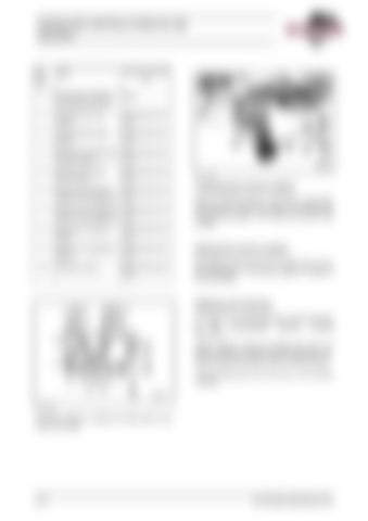
Pos. Fig. 2-54:
Fluid
Express coupling for
1
Diesel fuel for lefthand and righthand fuel tank
filling
2
Cooling fluid for left engine
Filling and/or draining
3
Cooling fluid for right engine
Filling and/or draining
4
Gearbox oil for left pump Filling and/or draitransfer gearbox ning
5
Gearbox oil for right pump transfer
6
Engine oil for lefthand Filling and/or draiengine oil tank (optional) ning
7
Engine oil for righthand Filling and/or draiengine oil tank (optional) ning
8
Engine oil for lefthand engine
Filling and/or draining
9
Engine oil for righthand engine
Filling and/or draining
Raising the service station
10
Hydraulic oil tank
Filling and/or draining
Disengage control knob (21) of valve (22), turn by 90° and press in. The service station is raised to the top position.
Filling and/or draining
Fig. 2-55:
Lowering the service station Draw out control knob (21, Fig. 2-55:) of valve (22) with rope (25). The service station is brought down to the lower position. Turn knob (21) by 90° and engage.
Refilling and draining For filling in or for draining fluids, unscrew the cap of the corresponding express coupling (Fig. 2-54:). Attach express coupling of filling hose from the service vehicle to the corresponding express coupling at the service station. Fill in or drain off fluid. Take off filling hose and refit cap on the express coupling.
Fig. 2-54:
A service vehicle is needed for filling and/or draining of the fluids.
2-54
BA RH200(3 668 880.00)-EN
