OPERATING INSTRUCTIONS RH 40 F Inspection and servicing CENTRAL LUBRICATING
All lubricating points connected to the system are greased at regular intervals. During the greasing cycle, indicator lamp (24, Fig. 3-95:) is lit up.
Design and function
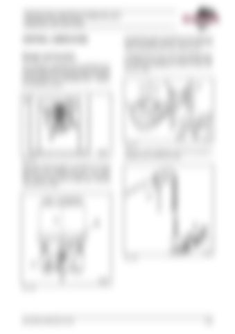
A grease pump (5, Fig. 3-97:) with attached grease container (6) pumps the grease through lines (7) to the main distributors (17 and 18, Fig. 3-97: and Fig. 3-98:).
The excavator is equipped with an automatic central lubricating system ensuring regular the regular supply of grease to all greasing points except those mentioned in the "Lubricating chart - Grease" for the backhoe bucket.
Fig. 3-97:
There is no main distributor (18) if the excavator is equipped with a backhoe bucket. Fig. 3-95:
When the electrical system is switched on with the key-switch, the indicator lamp (23, Fig. 3-95:) lights up and the lubricating system is activated. The indicator lamp (23) is visible after removing cover (20, Fig. 3-96:).
Fig. 3-98:
Fig. 3-96:
BA RH40F(3 668 020.01)-EN
3-85
