OPERATING INSTRUCTIONS RH 40 F Inspection and servicing Track tensioner
Function
Design
The tensioning system is under permanent pressure of ca. 100 bar / 1450 psi which keeps both tracks permanently tensioned. Pressure losses are compensated as soon as the engines have been started. Retensioning is not required.
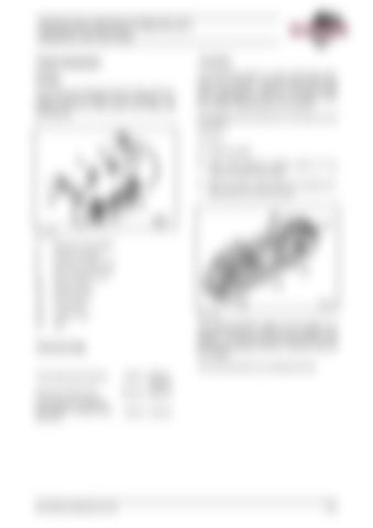
The tracks are tensioned with the help of the hydraulic pressure created during travelling. Fig. 3-89:and Fig. 3-90: show parts of the tracks and the tensioner:
For cleaning and servicing work, the tracks can be slackened. To do so: " stop the engine " open both pressure limiting valves (6, Fig. 3-90:) to slacken the tracks. " After the work, screw down the pressure limiting valves (6) to the limit stop.
Fig. 3-89:
4
Pressure accumulator
5
Pressure cylinder
6
Pressure limiting valve
9
Mini- measuring port
10
Support roller
11
Drive sprocket
12
Track roller
13
Crawler track
Fig. 3-90:
14
Idler
The pressure-limiting valves (6) are preset to a pressure of 250 bar / 3626 psi and sealed in this position. The lead seal must not be removed and the pressure setting of 250 bar / 3626 psi must not be changed.
Techncal data
The track tensioners are maintenance-free. Track tensioning pressure
Approx. 100 bar / 1450 psi
Pressure limiting valve
250 bar / 3626 psi
Gas pressure in pressure accumulator (nitrogen filling pressure)
80 bar / 1160 psi
BA RH40F(3 668 020.01)-EN
3-81
