4 - ASSEMBLY
17. Install the plugs (20) to the opposite end of the coupler hoses.
RAPH12WEL1192AA
12
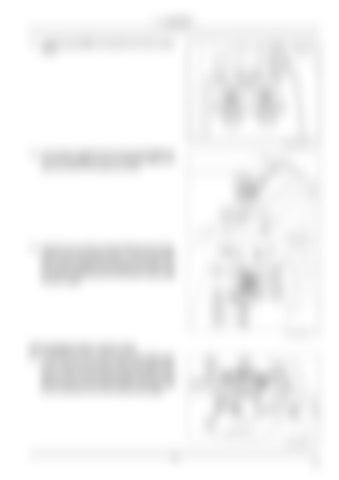
LEIL17WHL0072AB
13
LEIL17WHL0073AB
14
LEIL17WHL0075AB
15
18. If not present, install the hose clamp bracket (23) with the two bolts (26) and the two washers (15) to the right-hand side of the loader arm frame.
19. Place the two insulation clamps (13) facing each other, between the two coupler hoses. Insert the bolt (16) with a washer (15) through the tab on the loader arm. Place the two insulation clamps (13) onto the bolt. Add two washers (14) and secure with another washer (15) and the nut (5).
Unit equipped with 2 spool valve 20. On the top side of the hose clamp bracket (23) install the two tube mounting blocks (12) to the two coupler hoses. Place the two clamp cover plates (24) on the top of the tube mounting blocks (12). Insert the bolts (27) and secure with a washer (15) and locking nut (5) on the underside of the hose clamp bracket (23).
13 EN


