1 minute read
Remove the existing dump lines (A) and (E) from the main control valve.

from Case Locking hydraulics kit (Z-bar-XR) 521G 621G W110 D W130D loader Installation Instruction Manual

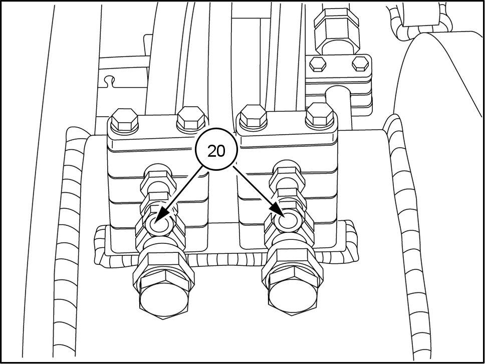
17. Install the plugs (20) the opposite end the coupler hoses.
18. not present, install the hose clamp bracket (23) with the two bolts (26) and the two washers (15) the right - hand side the loader arm frame.
19. Place the two insulation clamps (13) facing each other , between the two coupler hoses. Insert the bolt (16) with a washer (15) through the tab the loader arm.
Place the two insulation clamps (13) onto the bolt. Add two washers (14) and secure with another washer (15) and the nut (5) .
Unit equipped with 2 spool valve
20. the top side the hose clamp bracket (23) install the two tube mounting blocks (12) the two coupler hoses. Place the two clamp cover plates (24) the top the tube mounting blocks (12) . Insert the bolts (27) and secure with a washer (15) and locking nut (5) the underside the hose clamp bracket (23) .
RAPH12WEL1 192AA 12

LEIL17WHL0072AB 13

LEIL17WHL0073AB 14

LEIL17WHL0075AB 15