4 minute read
ASSEMBL Y
from Case Locking hydraulics kit (Z-bar-XR) 521G 621G W110 D W130D loader Installation Instruction Manual
2 - KIT CONTENT
Kit overview
NOTICE: check the items part numbers this kit, please refer the Parts Catalogue. NOTE: when referring the instructions for call out references, the numeric [example: (1) ] refers item (1) in the kit contents bill materials. The letter [example: (A) ] refers the component the unit, not a component in the kit contents bill materials. NOTE: special torque specifications are included in the instructions. torque specifications are not included in the instructions, use standard torque specifications. See your Service Manual Authorized Dealer if you need standard torque specifications.
Please read the complete instructions before starting assembly .
References right hand, left hand, front, and rear are determined seeing from the operator ’s seat. NOTE: the following table shows the items numbered in the installation instruction.
Item Description 1 Solenoid valve bracket 2 Solenoid valve 3 Hydraulic connector 4 W asher 1 1x24x2 5 Nut M10 6 W asher 6.6x18x1.6 7 Bolt M6x70 8 Nut 9 Straight hydraulic connector , ° elbow 11 T- fitting T ube mounting block Insulation clamp W asher 13.5x28x4 W asher 1 1x20x2 Bolt M10x40 Coupler tank hose Coupler pressure hose Coupler hose - bar) Plug Throttle check valve Coupler hose (XR) Hose clamp bracket Clamp cover plate Bolt M10x130 Bolt M10x25 Bolt M10x80 Bolt M10x1 Bolt M10x60 Diagnostic coupler Cable tie Quantity 1 1 2 2 7 4 2 2 1 2 1 4 2 2
1 1 1 2 2 2 2 1 4 4 2 4 4 4 1 4
3 - PRE-ASSEMBL Y
PREP ARING FOR ASSEMBL Y
Preparation
DANGER
Crushing hazard! you service the machine with the loader lift arms raised, always use the support strut. Remove the retaining pin and place the support strut onto the cylinder rod. Install the retaining pin into the support strut. Lower the lift arms onto the support strut. Failure comply will result death serious injury .
D0084A
Park the machine a firm, level surface. Empty the loader bucket. Raise the loader lift arms approximately 2.1 m ( 6.9 ). Stop the engine. Remove the retaining bolt and remove the support strut from the storage position.
Place the support strut onto the cylinder rod with the guide lock tab the top the cylinder . Position the guide lock tab toward the bucket. Install the retaining bolt entirely into the support strut using all threads. Slowly lower the lift arm onto the support strut.
LEIL12WHL0006BA 1

LEIL13WHL1244AA 2
W ARNING
Crushing hazard! Engage the safety lock link before service transport. Failure comply could result death serious injury .
154A
Install the transport / service link into the lock position. Refer the chapter “Safety information” contained in the Operator ’s Manual.

RCPH10WHL063BAL 3
W ARNING
Escaping fluid! Hydraulic fluid diesel fuel leaking under pressure can penetrate the skin and cause infection other injury . To prevent personal injury: Relieve all pressure before disconnecting fluid lines performing work the hydraulic system. Before applying pressure, make sure all connections are tight and all components are good condition. Never use your hand check for suspected leaks under pressure. Use a piece cardboard wood for this purpose. injured leaking fluid, see your doctor immediately . Failure comply could result death serious injury .
W0178A
W ARNING
Pressurized hydraulic fluid can penetrate the skin and cause severe injuries. Hydraulic fluid under extreme pressure. Rest the bucket attachment the ground. Shut the engine off, turn the key on, and move the hydraulic control lever through all movements several times relieve residual pressure the system. Failure comply could result death serious injury .
W0161A
W ARNING
Escaping fluid! not disconnect hydraulic quick coupler under pressurized conditions. Make sure all hydraulic pressure removed from the system before disconnecting hydraulic quick coupler . Failure comply could result death serious injury .
W0095A
W ARNING
Burn hazard! Before performing any service the hydraulic system, you must allow cool. Hydraulic fluid temperature should not exceed °C (104 °F). Failure comply could result death serious injury .
W0241A
Apply the parking brake and turn f the engine. Keep all non - authorized personnel clear the machine. T urn the ignition key the position. Pilot control switch must ON.

LEIL16WHL1571AA 4
Operate the control levers from right left and front rear approximately a dozen times relieve hydraulic line pressure and install vacuum pump hydraulic tank. T urn the ignition key the OFF position and remove the key . NOTICE: before carrying out any service work the hydraulic system, it is necessary allow the system cool (the temperature should not more than °C ( 104.0 °F ).
Open the engine hood. T urn the timed disconnect switch the OFF position. Remove all contaminants from hose and tube connections required disconnected. For identification purposes, label all disconnected electrical wires, hoses, and tubes. Plug and cap all open hose and tube connections. Ensure plugs and caps are clean and free debris.

LEIL16WHL1572AA 5
NOTE: before installation any hydraulic hose, tube fitting, make certain O- ring seals are properly installed and lubricated. 10. Loosen the filler cap the hydraulic oil tank release the air pressure in the hydraulic oil tank. 1 Drain the hydraulic oil tank.

LEIL16WHL0198AA 6
12. Loosen and remove the bolts and washers that fasten the access cover plate for the main control valve. Remove the cover plate.

LEIL13WHL1246AB 7
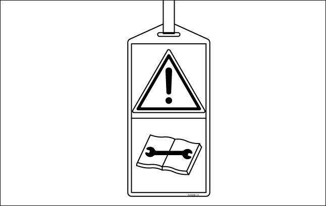
13. Attach a "DO NOT OPERA TE" maintenance tag. This tag can applied the cab door .

SP0043 8


