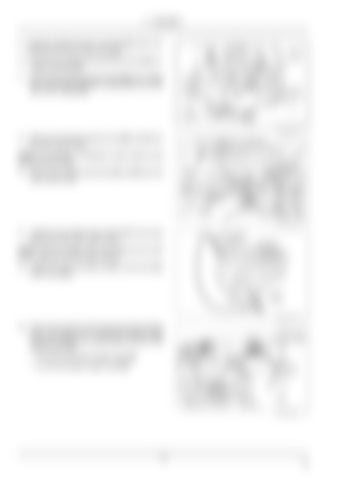
4 - ASSEMBLY
9. Install the straight hydraulic connector (9) and the T-fitting (11) to the main control valve (V). 10. Connect the coupler tank hose (17) to the straight hydraulic connector (9). 11. Connect the coupler pressure hose (18) to the T-fitting (11). Connect the diagnostic coupler (31) to the other end of the T-fitting (11).
LEIL16WHL0708AB
8
LEIL17WHL0125AB
9
12. Remove the existing hydraulic lines (B) and (C) from the main control valve. NOTE: this operation is necessary to gain access to the existing dump line (E). 13. Remove the existing dump lines (A) and (E) from the main control valve.
14. Install the two throttle check valves (21) to the dump spool port of the main control valve. NOTE: Insert the throttle check valve (21) into the main control valve port with the short end first. 15. Install the dump lines (A) and (E) to the two throttle check valve (21).
LEIL17WHL0126AB
10
LEIL17WHL0074AB
11
16. Drop one end of the coupler hoses through the oblong hole in the loader arm. Connect the coupler hoses to the two hydraulics connectors (3) on the top of the solenoid valve (2). • For Z-bar use shorter coupler hose (19). • For XR use longer coupler hose (22).
12 EN


