Engine This section has been organized into sub-sections which show a progression for the complete servicing of the engine. To service bottom-side components, the engine must be removed from the frame. To service top-side or left-side components, the engine does not have to be removed from the frame. NOTE: The manufacturer recommends the use of new gaskets, lock nuts, and seals and lubricating all internal components when servicing the engine. NOTE: A new ROV and an overhauled ROV engine require a “break-in” period. The first 10 hours (or 200 miles [320 km]) are most critical to the life of this ROV. Proper operation during this break-in period will help ensure maximum life and performance from the ROV. Instruct the customer to follow the proper break-in procedure as described in the Operator’s Manual.
VOR-502
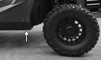
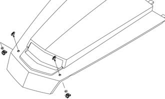
3. Remove the skid plate. Remove the screws (A) and nuts securing the rear hoop frame to the main frame. Remove the hoop frame assembly
SPECIAL TOOLS
A number of special tools must be available to the technician when performing service procedures in this section. Refer to the current Special Tools Catalog for the appropriate tool description. NOTE: When indicated for use, each special tool
will be identified by its specific name, as shown in the chart below, and capitalized. Description Magneto Rotor Remover Set Piston Pin Puller Spanner Wrench
p/n 0444-254
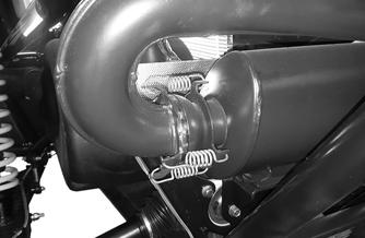
4. Remove the springs securing the muffler to the manifold.
Common Tool 0444-240
Surface Plate
Common Tool
V Blocks
Common Tool
Clutch Puller
VOR-501
0744-080
NOTE: Special tools are available from the Service Department.
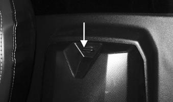
Removing Engine 1. Remove the seats, shift knob, handle, rear access console, and the center console. 2. Remove the rear cargo tray. Remove the three screws securing the rear of the cargo tray heat shield to the rear fascia heat shield.
30
XX242
5. Remove the three cap screws and nuts securing the muffler to the rear transaxle mount; then slide the muffler to the right and out from the vehicle.