16 minute read
Periodic Maintenance/Tune-Up

Tighten all nuts, bolts, and cap screws. Care must be taken that all calibrated nuts, bolts, and cap screws are tightened to specifications. It is advisable to lubricate certain components periodically to ensure free movement. Apply light oil to the components using the following list as reference: A.Accelerator Pedal Pivot/Cable Ends B.Brake Pedal Pivot C.Shift Cable SPECIAL TOOLS A number of special tools must be available to the technician when performing service procedures in this section. Refer to the current Special Tools Catalog for the appropriate tool description. NOTE: When indicated for use, each special tool
will be identified by its specific name, as shown in the chart below, and capitalized.
Description p/n
Compression Tester Kit Common Tool Oil Filter Wrench Common Tool Timing Light Common Tool
NOTE: Special tools are available from the Service
Department.
Air Filter
CLEANING AND INSPECTING FILTER CAUTION
Failure to inspect the air filter frequently if the vehicle is used in dusty, wet, or muddy conditions can damage the engine.
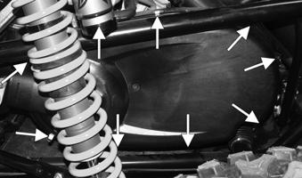
NOTE: The air filter is located above the engine and
can be accessed by removing the rear cargo tray.
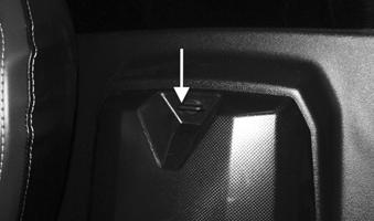
1.Remove dirt and debris from around the filter housing. 2.Pull the release tab out away from the filter housing.

XX227
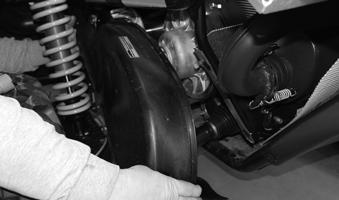
3.Rotate the end of the housing approximately 1/16 of a turn counterclockwise to release the cover from the air cleaner. 4.Pull the air cleaner element out of the air cleaner. NOTE: Once the filter has been removed, lightly
tap the filter to remove any dust particles or contaminants from the filter. If the filter is excessively covered in dust particles and contaminants, it must be replaced.
XX228
CAUTION
Do not use compressed air to clean the paper element. This may cause tears in the element and allow particles to enter the combustion chamber leading to accelerated engine wear.
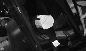
5.Plug the intake tube with a clean shop towel. Then clean the inside of the air cleaner body. 6.Remove the shop towel from the intake tube. Then place a new air cleaner element into the filter housing. Push the element into the housing until it is fully seated.

XX229
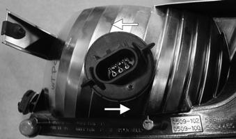
7.Reinstall the air filter cover, then turn it approximately 1/16 of a turn clockwise to seat it to the housing. Verify the duck bill drain is located at the bottom of the assembly. Then lock the cover to the housing by pressing the retainer tab inward toward the assembly. 8.Install the rear cargo tray.
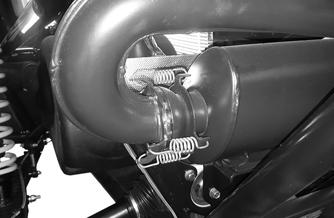
Spark Arrester
NOTE: The muffler has a spark arrester which
must be periodically cleaned. At the intervals shown in the Maintenance Schedule, clean the spark arrester using the following procedure.
! WARNING
Wait until the muffler cools to avoid burns
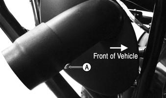
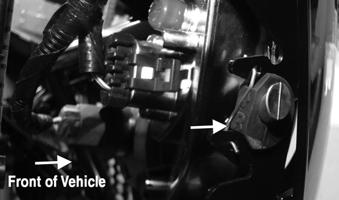
1.Remove the screw (A) securing the spark arrester assembly to the muffler.
XX081
2.Using a suitable brush, clean the carbon deposits from the screen taking care not to damage the screen. NOTE: If the screen or gasket is damaged in any
way, it must be replaced.

WC929
3.Install the spark arrester assembly and secure the screw. Tighten to 72 in.-lb (8.1 N-m).
Valve/Tappet Clearance
NOTE: To check/adjust clearance, see Engine —
Servicing Components.
Testing Engine Compression
NOTE: The engine should be warm (operating tem-
perature) and the battery fully charged for an accurate compression test.
NOTE: The rear cargo tray must be removed for
this procedure.
1.Remove spark plugs. See spark plugs section for proper procedure. 2.Attach the spark plug connectors to the ignition coils. Attach spark plugs to the ignition coils and ground the plugs on the cylinder heads well away from the spark plug holes.
CAUTION
Do not ground the spark plug on the cylinder head cover. The cover is made of magnesium and any contact with spark or electrical arc will severely pit the surface.
3.Attach the Compression Tester Kit. 4.While holding the throttle in the full-open position, crank the engine over with the electric starter until the gauge stops climbing (five to 10 compression strokes). Compression should be 217-261 psi (1500-1800 kPa). Verify the cylinder compression readings are within 10% of each other. 5.If compression is abnormally low, verify the following:
A.Starter cranks engine over (normal speed).
B.Gauge is functioning properly.
C.Throttle in the full-open position.
D.Valve/tappet clearance correct.
E.Engine warmed up.
6.If compression is still low, check for blown cylinder head gasket, valve leakage, or worn piston rings or cylinder (see Engine — Servicing Components).
Spark Plugs
NOTE: The rear cargo tray must be removed for
this procedure.
CAUTION
Before removing a spark plug, be sure to clean the area around the spark plug. Dirt could enter engine when removing or installing the spark plug.
! WARNING
Always wear safety glasses when using compressed air.
1.Using compressed air, blow any debris from around the ignition coils. Remove the spark plug connectors (B) from the ignition coils (A).
XX068
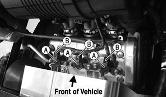
2.Remove bolts from ignition coils (A). Remove ignition coil (A). Remove spark plugs. A light brown insulator indicates the plug and fuel/air ratio are correct. A white or dark insulator indicates that the engine may need to be serviced. To maintain a hot, strong spark, keep the plug free of carbon. Adjust the gap to 0.7-0.8 mm (0.028-0.031 in.).

ATV-0051 ATV-0052
A new spark plug should be tightened 1/2 turn once the washer contacts the cylinder head. A used spark plug should be tightened 1/8-1/4 turn once the washer contacts the cylinder head.
Engine Oil — Filter
OIL — FILTER Change the engine oil and oil filter at the scheduled intervals. The engine should always be warm when the oil is changed so the oil will drain easily and completely. NOTE: The rear cargo tray must be removed to
access the oil tank and top of the engine.
1.Park the vehicle on level ground. 2.Loosen the oil level stick. Be careful not to allow contaminants to enter the opening.

XX230
3.Loosen the fill plug on top of the valve cover. Be careful not to allow contaminants to enter the opening.

XX231
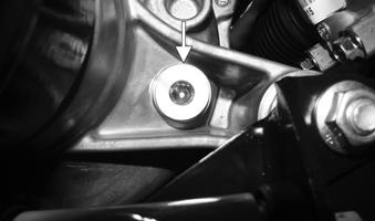
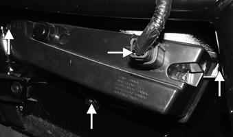
4.Remove the drain plug and crush washer from the bottom of the oil tank. Use a funnel to direct the oil into a drain pan.

XX232
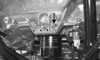
5.Remove the drain plug and washer from the bottom of the engine and drain the oil into a drain pan. NOTE: There is a “triangle” symbol cast into the oil
pan located next to the drain plug for identification purposes.
XX033A
6.Using the oil filter wrench and a ratchet handle (or a socket or box-end wrench), remove the old oil filter and dispose of properly. Verify the oil filter seal has been removed along with the filter. Do not re-use oil filter. NOTE: Clean up any excess oil after removing the
filter.
7.Apply new engine oil to the new oil filter seal; then install the new oil filter onto the engine. Tighten securely. 8.Install the engine drain plug and new washer.
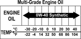
Tighten to 7.2 ft-lb (9.8 N-m). Install the oil tank drain plug and new washer. then tighten to 12 ft-lb (16 N-m). 9.Pour 2.70 US qt (2.55 L) of ACX All Weather synthetic oil into the oil tank. Install the dipstick. Install the fill plug on top of the valve cover. 10.Start the engine (while the vehicle is outside on level ground) and allow it to idle until at least one of the radiator fans cycles on and off. Check for any leaking oil. If oil is leaking, immediately stop the engine and correct the cause of the leak before proceeding. NOTE: The manufacturer recommends the use of
genuine lubricants.
NOTE: The oil level stick should NOT be threaded
into the oil tank for checking purposes
11.Turn the engine off and wait approximately one minute. Remove the dipstick from the oil tank and recheck the oil level. Add more oil if the level is not visible on the dipstick. The oil level MUST be within the operating range.
Front Differential — Transaxle Lubricant/Fluid
To change front differential lubricant, use the following procedure: NOTE: The fill plug is located on the front right side
of the differential.
1.Place the vehicle on level ground; then remove the fill plug.
XX116
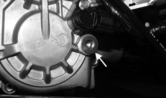
2.Drain the lubricant into a drain pan by removing the drain plug. Clean away any debris that may have accumulated onto the magnetic end of the plug.

XX117
3.After the lubricant has been drained, install the drain plug and tighten to 10-22 ft-lb (14-30 N-m). 4.Add SAE-approved 80W-90 hypoid gear lube into the fill plug hole. The lubricant level should be approximately level with the bottom of the plug threads. 5.Install the fill plug and tighten to 10-22 ft-lb (14-30 N-m). To change transaxle fluid, use the following procedure: NOTE: The fill plug is located on the front right side
of the transaxle.
NOTE: If the fluid is contaminated with water,
inspect the drain plug, fill plug, and/or bladder.
1.Place the vehicle on level ground; then remove the fill plug.
XX113
2.Drain the fluid into a drain pan by removing the drain plug. Clean away any debris that may have accumulated onto the magnetic end of the plug.

XX114
3.After the fluid has been drained, install the drain plug and tighten to 10-22 ft-lb (14-30 N-m). 4.Add Synthetic Transaxle Fluid with EP into the fill plug hole. The fluid level should be approximately level with the bottom of the plug threads. 5.Install the fill plug and tighten to 10-22 ft-lb (14-30 N-m).
Headlight — Taillight — Brake Light
HEADLIGHT BULB REPLACEMENT NOTE: The LED strips in the headlight assembly
are not individually replaceable. The entire assembly must be replaced as a component.
1.Remove hood 2.Remove the wiring harness connector (A) from the back of the headlight bulb (B). 3.Rotate the headlight bulb (B) counterclockwise to remove from the assembly.

XX069
4.Rotate the new headlight bulb (B) clockwise into headlight assembly. Reinstall wiring harness connector (A). 5.Adjust the headlight using the Checking/Adjusting
Headlight Aim instructions in this section.
1.Remove hood. 2.Remove the headlight retaining knob.

XX069A
3.Remove the wiring harness connectors. Remove the retainers on both sides of the headlight assembly that secure the headlight assembly.

XX070

XX071
4.Headlight assembly mounts in a C-shaped channel.
Slide headlight assembly toward the rear of the vehicle to release from the channel. 5.Remove headlight from rear housing of headlight assembly by turning counterclockwise.
XX072A
INSTALLING HEADLIGHT ASSEMBLY
1.Install headlight bulb from rear of headlight assembly by turning clockwise.

XX072
2.Headlight assembly mounts in a C-shaped channel.
Slide headlight assembly toward front of vehicle to mount into C-shaped channel. Install the retainers on both sides of the headlight assembly that secure the headlight assembly.
XX070A
XX071
3.Install the wiring harness connectors.
XX070B

4. Install the headlight retaining knob.
XX069A
5.Adjust the headlight using the Checking/Adjusting
Headlight Aim instructions in this section. REMOVING TAILLIGHT/BRAKE LIGHT NOTE: The LED taillights are not serviceable. The
entire assembly must be replaced as a component.
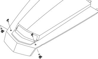
1.Remove the rear cargo tray. 2. Disconnect the wiring harness connector. Remove the screws securing the taillight to the fascia.

XX073
INSTALLING TAILLIGHT/BRAKE LIGHT
1.Install screws to the fascia. Connect the wiring harness connector.
XX073
CHECKING/ADJUSTING HEADLIGHT AIM The headlights can be adjusted vertically. The geometric center of the HIGH beam light zone is to be used for vertical aiming. 1.Position the vehicle on a level floor so the headlights are approximately 6.1 m (20 ft) from an aiming surface (wall or similar aiming surface).
XX029
NOTE: There should be an average operating load
on the vehicle when adjusting the headlight aim.
2.Measure the distance from the floor to the midpoint of each headlight.
3.Using the measurements obtained in step 2, make horizontal marks on the aiming surface directly in front of each headlight. 4.Switch on the lights. Make sure the HIGH beam is on. DO NOT USE LOW BEAM. 5.Observe each headlight beam aim. Proper aim is when the most intense beam is 5 cm (2 in.) below the horizontal mark on the aiming surface. 6.Adjust each headlight until correct aim is obtained by loosening (counterclockwise) the retaining knob; then pivot the assembly up or down. Once the correct level is achieved, tighten (clockwise) the retaining knob.
XX069A
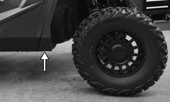
Hydraulic Brake System
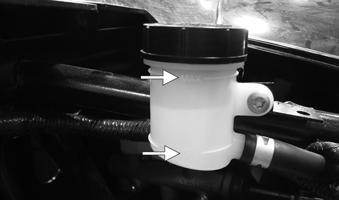
CHECKING The hydraulic brake system has been filled and bled at the factory. To check hydraulic brake system, use the following procedure. 1.With the vehicle in a level position and the tires properly inflated, check the fluid level in the reservoir. If the level in the reservoir is not above the MIN line, add DOT 4 brake fluid. NOTE: The brake fluid reservoir is located under-
neath the hood.
XX022
2.Press the brake pedal several times to check for a firm brake. If the brake is not firm, the system must be bled. 1.To bleed hydraulic brake system, use the following procedure:
A.Remove the brake fluid reservoir cover and fill the reservoir with DOT 4 brake fluid.
B.Install and secure the cover; then slowly press the brake pedal several times. C.Install one end of a clear hose onto the bleed screw farthest from the cylinder (right rear) and direct the other end into a container; then while holding slight pressure on the brake pedal, open the bleed screw and watch for air bubbles. Close the bleed screw before releasing the brake pedal.
Repeat this procedure until no air bubbles are present.
XX226
NOTE: During the bleeding procedure, watch the
reservoir very closely to make sure there is always a sufficient amount of brake fluid. If the fluid level gets low in the reservoir, refill the reservoir before the bleeding procedure is continued.
D.Repeat step C until the brake pedal is firm.
E.At this point, perform steps B, C, and D on the left rear bleed screw; then move to the right front bleed screw and follow the same procedure. Finish with the left front bleed screw.
2.Carefully check the entire hydraulic brake system to ensure that all hose connections are tight, the bleed screws are tight, the protective caps are installed, and no leakage is present.
INSPECTING HOSES Carefully inspect the hydraulic brake hoses for cracks or other damage. If found, the brake hoses must be replaced.
CAUTION
This hydraulic brake system is designed to use DOT 4 brake fluid only. If brake fluid must be added, care must be taken as brake fluid is very corrosive to painted surfaces.
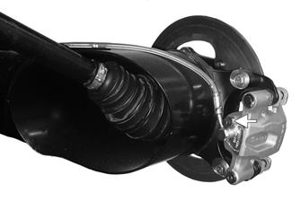
CHECKING/REPLACING PADS The clearance between the brake pads and brake discs is adjusted automatically as the brake pads wear. The only maintenance that is required is replacement of the brake pads when they show excessive wear. Check the thickness of each of the brake pads as follows. 1.Remove a wheel. 2.Measure the thickness of each brake pad.
WT220
3.If thickness of either brake pad is less than 1.0 mm (0.039 in.), the brake pads must be replaced. NOTE: The brake pads should be replaced as a set. 4.To replace the brake pads, use the following procedure:
A.Remove the cap screws securing the caliper holder to the knuckle (front) or the wheel bearing assembly (rear); then remove the pads from the caliper.
B.Install the new brake pads.
C.Secure the caliper holder to the knuckle with new “patch-lock” cap screws. Tighten to 35 ft-lb (48 N-m).

XX225
6.Install the wheel; then using a crisscross pattern, tighten the wheel nuts in 20 ft-lb (27 N-m) increments to a final torque of 95 ft-lb (129 N-m). 7.Burnish the brake pads (see Burnishing Brake Pads in this section).

BRAKE DISC Using a micrometer, measure the thickness of the brake disc in the contact surface. If thickness is 0.125-in. (3.2 mm) or less, the disc must be replaced. To replace the brake disc, see Drive and Brake Systems — Disc Brake.
Burnishing Brake Pads
Brake pads must be burnished to achieve full braking effectiveness. Braking distance will be extended until brake pads are properly burnished.
1.Choose an area large enough to safely accelerate the vehicle to 30 mph (48 km/h) and to brake to a stop. 2.Accelerate to 30 mph (48 km/h); then release the accelerator pedal and depress the brake pedal to decelerate to 0-5 mph (0-8 km/h). 3.Repeat procedure 20 times until brake pads are burnished. ! WARNING
Failure to properly burnish the brake pads could lead to premature brake pad wear or brake loss. Brake loss can result in severe injury or death.
Replacing V-Belt
NOTE: Drive belts require a break-in period (see
Drive Belt Break-In Procedure in the General Information/Foreword Section).
CAUTION
Failure to properly break-in a new drive belt will result in premature belt failure.
REMOVING
1.Loosen the clamp securing the cooling duct to the
CVT cover.

XX140
2.Unlatch the clamps securing the CVT cover.
XX108
3.Remove the CVT cover. When removing CVT cover, disconnect from cooling duct.
XX141
4.Install the Belt Removal Tool turning clockwise into the driven clutch. Remove the drive belt starting from the bottom of the driven clutch.

XX142
CHECKING Use the Drive Belt Gauge to identify any abnormal wear. Measure across the top of the V-belt (in multiple locations) using a Vernier caliper. Do not squeeze the belt as doing so may produce an inaccurate measurement. The V-belt must be at least 38.4 mm (1.5 in.) at any point. INSTALLING

1.Install the Belt Removal Tool into the driven clutch by turning clockwise. Install the drive belt starting from the bottom of the driven clutch making sure the directional arrows on the belt are aligned with engine rotation. 2.Remove the Belt Removal Tool by turning counterclockwise from the driven clutch. Place the transmission in neutral and rotate the driven clutch and drive belt by hand in a counterclockwise direction until the drive belt has reached the outermost point of the driven clutch. 3.Making sure the clutch cover gasket stays within the channel along the whole CVT cover housing install the CVT cover from the rear of the vehicle. 4.Latch the clamps securing the CVT cover.
XX108
5.Connect the cooling duct to the CVT cover; then install and tighten the clamp securing the cooling duct to the CVT cover.