12 minute read
General Information/Foreword

This Service Manual contains service, maintenance, and troubleshooting information for the 2020 Wildcat XX. The complete manual is designed to aid service personnel in service-oriented applications. This manual is divided into sections. Each section covers a specific vehicle component or system and, in addition to the standard service procedures, includes disassembling, inspecting, and assembling instructions. When using this manual as a guide, the technician should use discretion as to how much disassembly is needed to correct any given condition. This service manual is designed primarily for use by a CatMaster Basic Level technician. The procedures found in this manual are of varying difficulty, and certain service procedures in this manual require one or more special tools to be completed. The technician should use sound judgment when determining which procedures can be completed based on their skill level and access to appropriate special tools. NOTE: Whenever a part is worn excessively, cracked,
or damaged in any way, replacement is necessary.
When replacement of parts is necessary, use only genuine parts. They are precision-made to ensure high quality and correct fit. Refer to the appropriate Illustrated Parts Manual for the correct part number, quantity, and description. All publications and decals display the words Warning, Caution, Note, and At This Point to emphasize important information. The symbol !WARNING identifies personal safety-related information. Be sure to follow the directive because it deals with the possibility of serious personal injury or even death. A CAUTION identifies unsafe practices which may result in vehicle-related damage. Follow the directive because it deals with the possibility of damaging part or parts of the vehicle. The symbol NOTE: identifies supplementary information worthy of particular attention. The symbol AT THIS POINT directs the technician to certain and specific procedures to promote efficiency and to improve clarity. At the time of publication, all information, photographs, and illustrations were technically correct. Some photographs used in this manual are used for clarity purposes only and are not designed to depict actual conditions. Because products are constantly refined and improved, no retroactive obligation is incurred. All materials and specifications are subject to change without notice. Product Service and Warranty Department Arctic Cat
Specifications
NOTE: Specifications subject to change without notice.
CHASSIS
Dry Weight (approx) 821 kg (1812 lb) ROPS Tested Curb Weight 1179.4 kg (2600 lb) Length (overall) 345.4 cm (136 in.) Height (overall) 172.7 cm (68 in.) Width (overall) 162.6 cm (64 in.) Tire Size 30 x 10-15 — front 30 x 10-15 — rear Tire Inflation Pressure 14 psi (96.5 kPa) — front 22 psi (151.7 kPa) — rear
MISCELLANEOUS
Spark Plug Type NGK CR9EB Spark Plug Gap 0.7-0.8 mm (0.028-0.031 in.) Gas Tank Capacity 37.85 L (10 U.S. gal) Coolant Capacity (60% Antifreeze/40% 9.5 L (2.5 U.S. gal) Water Mixture) Front Differential Capacity 400 ml (13.5 fl oz)* Transaxle Capacity 1.2 L (40.5 fl oz) Engine Oil Capacity 2.55 L (2.70 U.S. qt) (approx. capacity at oil change) Compression Ratio 11.3:1 Gasoline (recommended) Regular gas 86 PON, 91 RON or higher/ethanol content not to exceed 10% Engine Oil (recommended) ACX All Weather (Synthetic) Front Differential Lubricant SAE-Approved 80W-90 Hypoid Transaxle Lubricant Synthetic Transaxle Fluid with EP Belt Width 38.4 mm Brake Fluid DOT 4 Taillight/Brake Light LED Headlight Halogen H13 with LED Electric Starter Type Constant Mesh
COOLING SYSTEM
Cooling Fan 1 On 194° F (90° C) Cooling Fan 1 Off 185° F (85° C) Cooling Fan 2 On 203° F (95° C) Cooling Fan 2 Off 194° F (90° C) Thermostat Opening Temperature 156.2-163.4° F (69-73° C)
ELECTRICAL SYSTEM
Ignition Coil Resistance (primary) 1.40 ohm ± 15% (secondary) 10,000 ohm ± 15% Ignition Coil Primary Voltage Battery Voltage Stator Coil Resistance 0.19 ohm ± 20% Pickup Coil Resistance 495 ohm ± 20% AC Magnetos Output 14 volts, 39 A @ 5000 RPM Alternator Output 65 amps Ignition Timing 8° BTDC @ 1500 RPM Intake Air Temperature Sensor 315 ohm @ 176° F (80° C) Coolant Temperature Sensor 5,740 ohm @32° F (0° C) 310-326 ohm @ 176° F (80° C) 183.6 ohm @ 212° F (100° C)
VALVES AND GUIDES
Valve Head Diameter (intake) (exhaust) 30.90-31.10 mm 25.90-26.10 mm
Valve/Tappet Clearance (intake) (cold engine) (max) (exhaust)
0.16 mm 0.22 mm Valve Guide/Stem (intake) 0.08 mm Clearance (max) (exhaust) 0.10 mm Valve Guide Inside Diameter (max) 4.550 mm Valve Head Thickness (min) 2.3 mm Valve Seat Angle 45° +15’/+30’ Valve Spring Free Length (min) 37.59 mm Valve Spring Tension @ 34.6mm 112.30-129.30 N (25.25-29 lb) * Visible at plug threads.
Piston/Cylinder Clearance 0.035-0.060 mm (max) 0.120 mm Cylinder Bore 80.000-80.010 mm Piston Diameter 79.950-79.965 mm Bore x Stroke 80.0 x 66.2 mm Cylinder Trueness (max) 0.05 mm Piston Ring End Gap Installed (Top) 0.15-0.25 mm (2nd) 0.30-0.45 mm (Oil) 0.10-0.35 mm Piston Ring Side Clearance Installed (Top) 0.030-0.065 mm (2nd) 0.020-0.055 mm (Oil) 0.040-0.140 mm Piston Ring Groove Width (1st/2nd) 1.202-1.204 mm (Oil) 2.501-2.503 mm Piston Ring Thickness (1st/2nd)1.170-1.195 mm Piston Pin Bore (max) 19.045 mm Piston Pin Outside Diameter (min) 18.971 mm
CRANKSHAFT
Connecting Rod (small end diameter) 19.005-19.018 mm (big end diameter) 41.00-41.018 mm Crankshaft Runout (max) 0.05 mm Crankshaft Thrust Clearance 0.05-0.25 mm
Torque Specifications
Torque Tolerance
ft-lb N-m
0-15 0-20.3 ±20% 16-39 21.7-52.9 ±15% 40+ 54.2+ ±10%
Part Part Bolted to
EXHAUST COMPONENTS Torque ft-lb N-m
Manifold Engine 16 22 Muffler Transaxle Bracket 16 22 Spark Arrester Muffler 72 in-lb. 8 O2 Sensor Manifold 20 27 BRAKE COMPONENTS
Brake Disc Hub 16 22 Brake Hose Caliper 20 27 Brake Hose Master Cylinder 20 27 Brake Hose Frame 8 11 Master Cylinder Frame 25 34 Rear Caliper**** Bearing Housing 35 48 Front Caliper**** Knuckle 35 48 Remove Reservoir Frame 8 11 Front Brakeline Clip Upper A-Arm 6 8 Brake Pedal Frame 18 25 SUSPENSION COMPONENTS (Front)
A-Arm (Upper) Frame 75 102 A-Arm (Lower) Frame 75 102 A-Arm (Upper) Knuckle 75 102 A-Arm (Lower) Knuckle 75 102 Knuckle Tie Rod End 42 57 Shock Absorber**** Frame 75 102 Shock Absorber**** A-Arm 75 102 Knuckle Assembly** Axle 250 339 Sway Bar Mount Frame 42 57 Sway Bar Link A-Arm 35 48 SUSPENSION COMPONENTS (Rear)
Sway Bar Mount Frame 35 48 Sway Bar Sway Bar Link 35 48 Sway Bar Link Trailering Arm 35 48 Trailering Arm Frame 170 230
Part Part Bolted to Torque ft-lb N-m SUSPENSION COMPONENTS (Rear) (continued)
Bearing Housing Assembly Trailering Arm 35 48 Shock Trailering Arm 65 88 Shock Frame 65 88 Hub** Axle 250 339 Trailering Arm Rod End Trailering Arm 90 122 STEERING COMPONENTS
Steering Rack Mount Bracket 20 27 Mount Bracket Frame 20 27 EPS Bracket EPS Unit 35 48 Lower Steering Shaft (Splined End)Steering Rack 35 48 Lower Steering Shaft (Adj. Yoke) Self 35 48 Lower Steering Shaft (Upper EPS Unit 35 48 Splined End) Upper Steering Shaft (Splined End)EPS Unit 20 27 Upper Steering Shaft (Adj. End) Self 35 48 Tilt Steering Sub Assembly Frame 20 27 Tilt Steering Shock Frame 8 11 Steering Shaft** Steering Wheel 25 34
SEAT BELT ASSEMBLY
Seat Belt Retractor Frame 60 82 Seat Belt Flange Frame 60 82 Seat Belt Buckle Frame 60 82 Seat Belt Rear ROPS 35 48 SHIFTER ASSEMBLY
Shift Knob Shift Lever 12 16 Shift Cable End Shift Lever 8 11 Shift Cable Threads Bracket/Transaxle 20 27 Shift Cable Bracket Transaxle 6 8 Shift Axle Shift Bracket 8 11 COOLING ASSEMBLY
Upper Radiator Bracket Frame 14 19 P-Clamp Frame 8 11 Overflow Bottle Support Bracket 8 11 Lower Radiator Bracket Frame 14 19 Radiator Fan Radiator Shroud 6 8 Shroud Assembly Radiator 8 11 CLUTCH ASSEMBLY
Drive Clutch Engine 60 81 Drive Clutch Fan Drive Clutch 60 in-lb. 7 Cam Arm Drive Clutch 50 in-lb. 6 Spider Stationary Sheave 250 339 Clutch Cover Movable Sheave 120 14 in-lb. Torque Bracket Movable Sheave 120 14 in-lb. Driven Clutch Transaxle 60 82
ENGINE/TRANSAXLE COMPONENTS
Engine Cradle Engine 35 48 Engine/Transaxle Mid Mount Cradle 35 48 Engine Mid Mount 65 88 Front Mount Engine Cradle 35 48 Isolator Front Mount 35 48 Isolator Frame/Rear Hanger 35 48 Transaxle Mid Mount 65 88 Mount Bracket Mid Mount 35 48 Transaxle Rear Mount 35 48 Isolator Rear Mount 35 48 Rear Hanger Frame 35 48 FRAME/ROPS COMPONENTS
Rear ROPS Assembly Frame 35 48 Lower Front Skid Frame 65 88 ROPS Frame 35 48 Front ROPS Rear ROPS 35 48 Lower Air Dam Lower Front Skid 8 11 Headlight Mount Frame 8 11
Shift Support Frame 20 27 Tire Hold Down Bracket Frame 20 27 Cargo Mount Frame 8 11 * w/Oil ** w/Red Loctite #271 *** w/Green Loctite #270 **** w/“Patch-Lock” ***** w/Anti-Seize
Torque Conversions (ft-lb/N-m)
Drive Belt Break-In Procedure
ft-lb N-m ft-lb N-m ft-lb N-m ft-lb N-m 1 1.4 26 35.4 51 69.4 76 103.4 2 2.7 27 36.7 52 70.7 77 104.7 3 4.1 28 38.1 53 72.1 78 106.1 4 5.4 29 39.4 54 73.4 79 107.4 5 6.8 30 40.8 55 74.8 80 108.8 6 8.2 31 42.2 56 76.2 81 110.2 7 9.5 32 43.5 57 77.5 82 111.5 8 10.9 33 44.9 58 78.9 83 112.9 9 12.2 34 46.2 59 80.2 84 114.2 10 13.6 35 47.6 60 81.6 85 115.6 11 15 36 49 61 83 86 117 12 16.3 37 50.3 62 84.3 87 118.3 13 17.7 38 51.7 63 85.7 88 119.7 14 19 39 53 64 87 89 121 15 20.4 40 54.4 65 88.4 90 122.4 16 21.8 41 55.8 66 89.8 91 123.8 17 23.1 42 57.1 67 91.1 92 125.1 18 24.5 43 58.5 68 92.5 93 126.5 19 25.8 44 59.8 69 93.8 94 127.8 20 27.2 45 61.2 70 95.2 95 129.2 21 28.6 46 62.6 71 96.6 96 130.6 22 29.9 47 63.9 72 97.9 97 131.9 23 31.3 48 65.3 73 99.3 98 133.3 24 32.6 49 66.6 74 100.6 99 134.6 25 34 50 68 75 102 100 136
New drive belts require a break-in period of 25 miles (40 km). During this period, drive the vehicle for 25 miles (40 km) at 3/4 throttle or less while varying throttle position (but not exceeding 40 mph [64 km/h]). By varying throttle position, the exposed cord on the side of a new belt will be conditioned allowing the drive belt to gain its optimum flexibility and will extend drive belt life.
FILLING GAS TANK ! WARNING
Always fill the gas tank in a well-ventilated area. Never add fuel to the gas tank near any open flames or with the engine running. DO NOT SMOKE while filling the gas tank.
Since gasoline expands as its temperature rises, the gas tank must be filled to its specified capacity only. Expansion room must be maintained in the tank particularly if the tank is filled with cold gasoline and then moved to a warm area.
! WARNING
Do not overflow gasoline when filling the gas tank. A fire hazard could materialize. Always allow the engine to cool before filling the gas tank.
Tighten the gas tank cap securely after filling the tank.
RECOMMENDED GASOLINE The recommended gasoline to use in this vehicle is regular unleaded gasoline with a pump octane number (PON) of 86 or higher, or research octane number (RON) of 91 or higher. If knocking or pinging occurs, use a different brand of gasoline or premium unleaded gasoline. Oxygenated gasolines containing up to 10% ethanol are acceptable gasolines. Gasolines containing any amount of methanol are not recommended. When using ethanol-blended gasoline, it is not necessary to add a gasoline antifreeze since ethanol will prevent the accumulation of moisture in the fuel system.
RECOMMENDED ENGINE OIL The recommended oil to use is ACX All Weather Synthetic engine oil, which has been specifically formulated for use in this engine. Although ACX All Weather Synthetic engine oil is the only oil recommended for use in this engine, use of any API-certified SM 0W-40 oil is acceptable. ! WARNING
Do not over-fill the gas tank.
CAUTION
Do not use white gas. Only approved gasoline additives should be used.
OILCHARTJ
RECOMMENDED FRONT DIFFERENTIAL LUBRICANT The recommended lubricant is the manufacturer-branded Gear Lube or an equivalent gear lube which is SAE-approved 80W-90 hypoid. This lubricant meets all of the lubrication requirements of the vehicle front differential.
RECOMMENDED TRANSAXLE LUBRICANT The recommended transaxle lubricant is Synthetic Transaxle Fluid with EP. This lubricant meets all of the lubrication requirements of this vehicle.
CAUTION
Any lubricant used in place of the recommended lubricant could cause serious front differential damage.
CAUTION
Any lubricant used in place of the recommended lubricant could cause serious transaxle damage.
Preparation for Storage
The manufacturer recommends the following procedure to prepare the vehicle for storage:
1.Clean the seat cushions with a damp cloth and allow to dry. 2.Clean the vehicle thoroughly by washing dirt, oil, grass, and other foreign matter from the entire vehicle. Allow the vehicle to dry thoroughly. DO NOT get water into any part of the engine or air intake. 3.Either drain the gas tank or add a fuel stabilizer to the gas in the gas tank. 4.Clean the interior of the air filter housing. 5.Plug the hole in the exhaust system with a clean cloth. 6.Apply light oil to the upper steering shaft bushing and plungers of the shock absorbers.
CAUTION
Prior to storing this vehicle, it must be properly serviced to prevent rusting and component deterioration.
7.Tighten all nuts, bolts, cap screws, and screws. Care must be taken that all calibrated nuts, cap screws, and bolts are tightened to specifications. 8.Fill the cooling system to the bottom of the stand pipe in the radiator neck with properly mixed coolant. 9.Disconnect the battery cables (negative cable first); then remove the battery, clean the battery posts and cables, and store in a clean, dry area. NOTE: For storage, use a battery maintainer or
make sure the battery is fully charged (see Battery section in this manual).
10.Store the vehicle indoors in a level position.
CAUTION
Avoid storing outside in direct sunlight and avoid using a plastic cover as moisture will collect on the vehicle causing rusting.
Preparation after Storage
Taking this vehicle out of storage and correctly preparing it will ensure many miles and hours of trouble-free riding. The manufacturer recommends the following procedure: 1.Clean the vehicle thoroughly. 2.Clean the engine. Remove the cloth from the exhaust system. 3.Check all control wires and cables for signs of wear or fraying. Replace if necessary. 4.Change the engine oil and filter. 5.Check the coolant level and add properly mixed coolant as necessary. 6.Charge the battery; then install. Connect the battery cables making sure to connect the positive cable first.
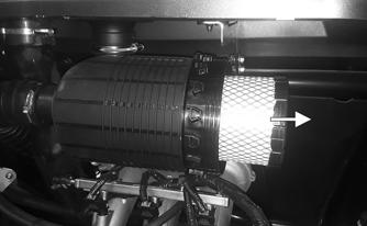
7.Check the entire brake systems (fluid level, pads, etc.), all controls, headlights, taillight, brake light, and headlight aim; adjust or replace if necessary. 8.Check the tire pressure. Inflate to recommended pressure as necessary. 9.Tighten all nuts, bolts, cap screws, and screws making sure all calibrated nuts, cap screws, and bolts are tightened to specifications. 10.Make sure the steering moves freely and does not bind. 11.Check the spark plugs. Clean or replace as necessary. 12.Check the air filter and the air filter housing. Clean or replace as necessary.
CAUTION