55 minute read
Engine

This section has been organized into sub-sections which show a progression for the complete servicing of the engine. To service bottom-side components, the engine must be removed from the frame. To service top-side or left-side components, the engine does not have to be removed from the frame. NOTE: The manufacturer recommends the use of
new gaskets, lock nuts, and seals and lubricating all internal components when servicing the engine.
NOTE: A new ROV and an overhauled ROV engine
require a “break-in” period. The first 10 hours (or 200 miles [320 km]) are most critical to the life of this ROV. Proper operation during this break-in period will help ensure maximum life and performance from the ROV. Instruct the customer to follow the proper break-in procedure as described in the Operator’s Manual.
SPECIAL TOOLS A number of special tools must be available to the technician when performing service procedures in this section. Refer to the current Special Tools Catalog for the appropriate tool description. NOTE: When indicated for use, each special tool
will be identified by its specific name, as shown in the chart below, and capitalized.
Description p/n
Magneto Rotor Remover Set 0444-254 Piston Pin Puller Common Tool Spanner Wrench 0444-240 Surface Plate Common Tool V Blocks Common Tool Clutch Puller 0744-080
NOTE: Special tools are available from the Service
Department.
Removing Engine
1.Remove the seats, shift knob, handle, rear access console, and the center console. 2.Remove the rear cargo tray. Remove the three screws securing the rear of the cargo tray heat shield to the rear fascia heat shield.

VOR-502
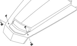
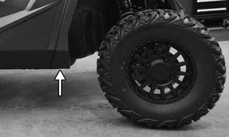
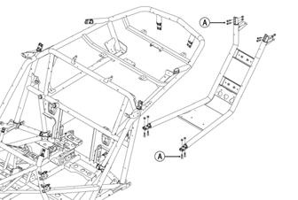
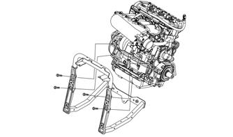
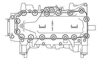
3.Remove the skid plate. Remove the screws (A) and nuts securing the rear hoop frame to the main frame.
Remove the hoop frame assembly
VOR-501
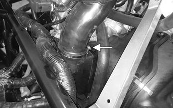
4.Remove the springs securing the muffler to the manifold.
XX242
5.Remove the three cap screws and nuts securing the muffler to the rear transaxle mount; then slide the muffler to the right and out from the vehicle.
XX259

6.Remove all screws securing the rear cargo tray exhaust heat shield to the frame; then remove the heat shield assembly rearward and out of the vehicle.
XX261

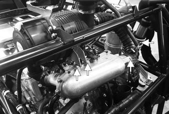
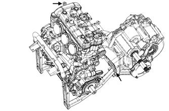
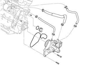
7.Remove the six nuts attaching exhaust header to engine; then disconnect the oxygen sensor from the main harness.


XX260
8.Pull exhaust header straight back until exhaust header is free from exhaust stud bolts on engine.
Remove manifold from vehicle. Account for three gaskets. 9.Lift the vehicle off the ground and remove the tires; then remove the retaining plate, castle nut, and washers securing the outer portion of the axles. 10.Locate the exposed set screw for the lock and rotate the axle into a position where you can access it with a 4 mm Allen wrench.
XX269
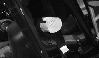
11.Turn the set screw a 1/4 turn counterclockwise to unlock the pin. Do not turn it more than1/4 turn. 12.Firmly grasp the inner cup and pull the axle from the transaxle. 13.Support the swing arm by a hydraulic jack or similar tool. Disconnect the sway bar and upper shock mount. This will allow the swing arm to move down, allowing for space to remove the axle from the vehicle. 14.Remove the nuts securing the seat belt retractors to the frame; then remove the screws securing the outer rear side panels. 15.Disconnect the main harness from the ECM; then remove both PDMs from the rear splash panel.
Remove the screws securing the rear splash panel to the frame. Remove the panel.
XX270
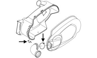
16.Loosen the clamp securing the clutch inlet duct to the
CVT inner cover; then remove the duct.

XX271
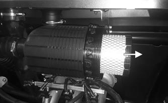
17.Remove the oil hose from the throttle body boot; then loosen the clamp securing the boot from the throttle body. 18.Remove the two screws securing the air cleaner bracket to the throttle body. Remove the air cleaner as an assembly.
XX283
19.Disconnect the main wiring harness from the TMAP sensor, the coils, and the injectors; then move the harness out of the way.
XX284
23.Using a suitable support jack supporting under the engine/transaxle assembly, remove the two cap screws and limiter washers securing the front engine mount to the frame.

XX286
24.Remove the four cap screws and nuts securing the transaxle mount to the frame.
XX284
20.Drain the oil (see Engine Oil — Filter sub-section in the Periodic Maintenance/Tune-Up section) and the cooling system (see the Liquid Cooling System section). 21.Remove all coolant hoses and oil hoses from the engine.

XX444
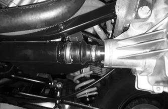
25.Remove the two clamps securing the coupler boot around the transaxle shaft and the mid prop shaft.
XX245
26.Carefully remove the engine/transaxle assembly out the rear of the vehicle. 27.Remove the CVT cover, drive clutch, drive belt, driven clutch, and the inner CVT clutch cover. 28.Remove the cap screws, washers, and spacers securing the alternator guard; then loosen the cap screw securing the alternator to the bracket. Loosen the belt and remove the belt.

XX308
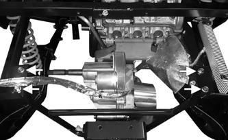
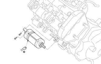
29.Remove the cap screw securing the starter motor cable to the motor.
VOR-515
31.Remove the two cap screws securing the rear of the engine to the mid transaxle mount; then carefully remove the engine free from the cradle, mount, and the transaxle.
XX245
Installing Engine
1.Before installing the engine, be sure the starter motor and cables are installed and secured to the engine.
XX378

30.Remove the four cap screws securing the engine cradle to the front of the engine.
XX378
2.Position the engine within the front two mounting positions in the cradle and the two mounting locations in the mid transaxle mount. Loosely secure the front of the engine to the cradle using the existing cap screws.
3.Thread in the existing cap screws to secure the rear of the engine to the mid transaxle mount; then tighten the driver-side cap screw to 65 ft-lb (88.4 N-m).
XX245
4.On the passenger side, back out the adjuster nut (A) against the engine mount to 15 ft-lb (20.4 N-m); then tighten the jam nut (B) to 60 in.-lb (6.8 N-m).
Tighten the passenger side cap screw to 65 ft-lb (88.4
N-m).
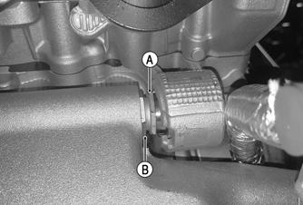
XX445
5.Secure the front of the engine cradle to the engine using the existing cap screws. Tighten to 35 ft-lb (47.6 N-m) starting with the bottom right; then top right; then bottom left; and finally top left.
VOR-515
6.Install the belt around the pulley on the engine and the alternator; then apply tension to the belt using the alternator. Secure using the cap screw. Tighten to 25 ft-lb (34 N-m).
XX308
7.Using a suitable lift, position the engine/transaxle assembly up into the frame aligning the transaxle shaft into the mid prop shaft. 8.Secure the rear transaxle mount to the frame using the existing cap screws and nuts. Tighten to 35 ft-lb (47.6 N-m) starting with the left side first and then the right side.

XX444
9.Align the two mounting locations of the front engine mount with the two rubber engine mounts on the frame. Secure using the existing cap screws and limiter washers. Tighten to 35 ft-lb (47.6 N-m).
XX286
10.Install the boot around the transaxle shaft and the mid prop shaft. Secure using two new clamps.
XX245
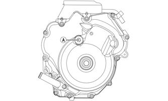
11.Secure the ground cable to the magneto cover using the existing screw. Tighten to 8 ft-lb (10.9 N-m).

XX380
15.Connect the main wiring harness to the TMAP sensor, the coils, and the injectors. Press the white push mounts into the injector rail. Cable tie wires as needed.
XX284
12.Connect all oil and coolant hoses to the engine.
Secure using the existing clamps. 13.Install the intake manifold assembly to the engine using the existing clamps. Tighten to 30 in.-lb (3.4 N-m).
XX284
16.Position the air cleaner bracket onto the intake manifold. Secure using the two screws (threads coated with blue Loctite #243). Tighten to 8 ft-lb (10.9 N-m). 17.Install the oil separator vent line to the fitting on the throttle body boot, secure using the clamp; then secure the throttle body boot to the intake manifold using the existing clamp. Tighten securely.
XX379

14.Secure the intake manifold to the engine cradle using the existing nuts. Tighten to 10 ft-lb (13.6 N-m).
XX283
18.With the gaskets positioned on the engine and on the transaxle, secure the inner CVT cover to the engine and the transaxle using the existing screws. Tighten to 8 ft-lb (10.9 N-m) using a crisscross pattern.
XX244
NOTE: The screws used to secure the cover to the
engine are p/n 1423-468 and the screws securing the cover to the transaxle are p/n 1423-220.
19.Clean the crankshaft end along with the drive clutch bore using parts cleaner; then place the drive clutch into position on the crankshaft.
CAUTION
When installing the drive clutch, do not tighten the cap screw with any kind of impact tool. Tighten cap screw using a hand torque wrench only. Failure to do so could result in stationary sheave damage.
20.Using the Drive Clutch Spanner Wrench and Drive
Clutch Bolt Tool, secure using the cap screw and high collar washer. Tighten to 60 ft-lb (81.6 N-m). 21.Place the movable driven sheave onto the driveshaft.
Install the shim(s); then install the stationary sheave onto the shaft; then, while holding the sheave, loosely secure the sheave using the existing washer (cupped toward the sheave) and cap screw. Tighten the cap screw to 60 ft-lb (81.6 N-m). Install the drive belt.

SNO-547
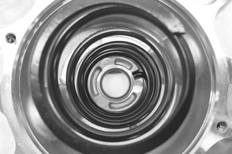
22.Making sure the clutch cover gasket stays within the channel along the whole CVT cover housing, install the CVT cover starting from the rear of the vehicle. 23.Latch the clamps securing the CVT cover. 24.Connect the cooling duct to the CVT cover; install and tighten the clamp securing the cooling duct to the CVT cover.
VOR-506
25.Secure the duct to the CVT inner cover using the existing clamp. Tighten securely.

XX271
26.Position the rear splash panel around the frame tubes; then secure using the existing screws. Tighten securely. 27.Route the main harness connectors up to the ECM and make sure they lock into position. Install the
PDMs into the two brackets on the panel.
XX270
28.Install the seat belt retractors to the frame using the existing nut. Tighten to 60 ft-lb (81.6 N-m). 29.Install the outer rear panels using the existing screws. Tighten securely. 30.Install the axles into the transaxle and through the trailing arm.
31.Install the shocks using the existing cap screws and nuts. Tighten to 65 ft-lb (88.4 N-m). 32.Align the manifold with the engine stud bolts. Push exhaust header into place so the engine exhaust studs go through the exhaust header. 33.Starting in the middle, secure using the existing nuts.
Tighten to 16 ft-lb (21.8 N-m).
XX260
34.Connect the oxygen sensor to the main harness; then secure the sensor wires using two push-mount cable ties. 35.Install the rear cargo tray heat shield assembly to the frame using the existing screws. Tighten securely. 36.Position the muffler with the manifold and secure using the existing springs; then secure the muffler to the transaxle bracket using the existing cap screws, washers, and nuts. Tighten to 16 ft-lb (21.8 N-m).
XX259
37.Install the rear hoop frame and secure using the existing screws and new nuts. Tighten to 35 ft-lb (47.6 N-m). 38.Install the skid plate and the rear cargo tray. 39.Install the cooling system and the oil system.
Servicing
This engine sub-section has been organized to show a progression for servicing of the engine. For consistency purposes, this sub-section shows a complete and thorough progression; however, for efficiency it may be preferable to disassemble only those components needing to be addressed. Also, some components may vary from model to model. The technician should use discretion and sound judgment. SPECIAL TOOLS A number of special tools must be available to the technician when performing service procedures in this engine section. NOTE: When indicated for use, each special tool
will be identified by its specific name, as shown in the chart below, and capitalized.
Description p/n
Ball Hone Common Tool Flywheel Puller Kit 0744-083 Piston Pin Puller Common Tool V Blocks Common Tool Drive Clutch Spanner Wrench 0644-136 Ring Compressor Common Tool MAG Cover Removal Cap Screw 2623-100
NOTE: Special tools are available from the Service
Department.
Disassembling
1. With the engine secured to a suitable engine stand, remove the cap screws securing the ignition coils to the valve cover. Remove the coils and the spark plugs.
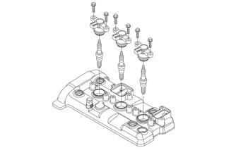
VOR-519
2.Remove the four Allen-head screws and gaskets securing the valve head cover to the cylinder head; then remove the cover. Account for the gasket.
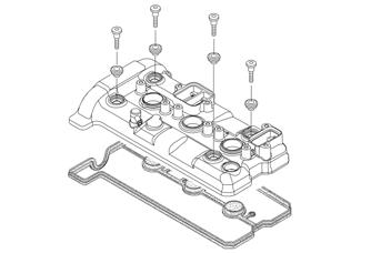
VOR-518
3. Remove plastic plug (A) from the MAG cover.
VOR-517
NOTE: The engine cylinders are numbered #1, #2,
and #3 from the PTO to the MAG.
SNO-318A

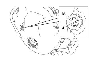
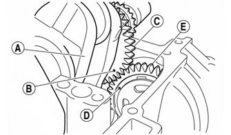
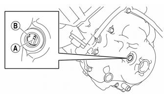
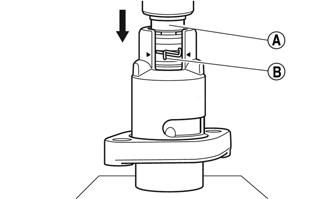
4.Obtain top-dead-center (TDC) by rotating the crankshaft (clockwise) until the mark (A) on the magneto rotor is aligned with the pointer on the magneto cover (B) and the #3 piston is at TDC using the cap screw that secures the pulley to the end of the crankshaft.
SNO-279A
NOTE: TDC on the compression stroke can be
found when the camshaft lobes for cylinder #3 (MAG side) are turned away from each other.
NOTE: At this point, if the technician’s objective is
to service the valves, proceed to Servicing Components — Valves in this sub-section.
5.Remove the two cap screws securing the starter motor assembly to the crankcase; then remove the starter motor.
SNO-730
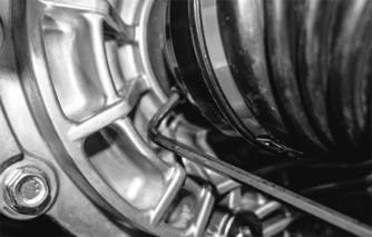
6. Loosen the cap screw that is securing the alternator output assembly to the crankshaft until access to the screw-in lip seal is achieved; then using a 41 mm crowfoot wrench, remove the lip seal from the magneto cover. Remove the entire assembly from the engine.

XX315
7. Remove the Allen-head screws securing the MAG cover to the crankcase.

SNO-752
8. Thread the MAG Cover Removal Cap Screw into the timing mark hole; then carefully pull the MAG cover from the crankcase. Account for two dowel pins and a gasket.


YM-203
! WARNING
When removing the cover be sure to keep hands away from being pinched between the cover and the case.

YM-204
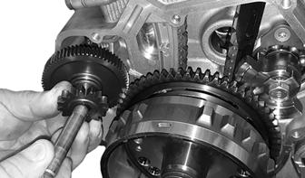
9.Remove the starter gear and shaft.
YM-205
10.Using Flywheel Puller, remove the flywheel from the crankshaft. Account for the key in the crankshaft.
YM-206
YM-207
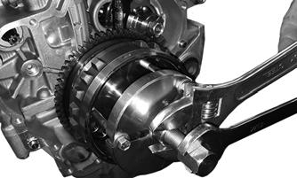
11.Thread the primary sheave bolt into the end of the crankshaft and pull the output shaft assembly from the engine. 12. Remove the Allen-head screws securing the water pump assembly to the crankcase; then remove the assembly. Account for two dowel pins and two gaskets.

SNO-753
NOTE: The engine may have to be rotated for the
water pump gear to clear the counterbalancer.
13.Disconnect all hoses from the oil cooler; then remove the Allen-head screws securing the oil cooler assembly to the engine. Remove the assembly.

VOR-521
14.Remove the two Allen-head screws securing the chain tensioner to the cylinder assembly. Remove the tensioner and gasket. 15.Remove the cap screws securing the exhaust camshaft cap (A), intake camshaft cap (B), and the camshaft (C). Account for the dowel pins that may still be connected to the camshaft caps. NOTE: To prevent damage to the cylinder head,
camshafts, or camshaft caps, loosen the camshaft cap screws in stages and in a crisscross pattern working in from the outside.
SNO-756
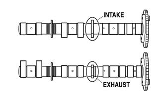
16.Remove the exhaust and intake camshafts from the engine.
SNO-757
17.Remove the eight cap screws (#3-10) and two
Allen-head screws (#1 and #2). Remove the head and account for the gasket and dowel pins. NOTE: Loosen the cap screws in the proper
sequence as shown. Loosen each cap screw 1/2 of a turn at a time. After all of the cap screws are fully loosened, remove them.
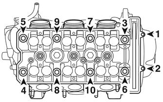
SNO-758
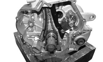
18.Remove the cap screws securing the timing chain tension guides to the engine; then remove the guides.
YM-016A
19. Tip the engine upside down; then remove the cap screws securing the oil pan to the crankcase. Using a soft hammer, gently tap around the oil pan until it separates. Account for the oil pan gasket and two dowel pins.
SNO-759
NOTE: Note the location of the different-length cap
screws for assembling purposes.
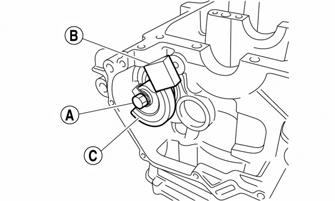
20.Remove the two cap screws securing the oil pump chain guide. Remove the cap screw securing the oil pump driven gear (A) to the oil pump using the sprocket holding tool (B); then remove the oil pump chain and timing chain from the crankshaft.

YM-020A
22.Loosen the cap screws in decreasing numerical order of the embossed numbers on the crankcase. Loosen each bolt 1/4 of a turn at a time. After all screws are loosened, remove the screws. Remove the lower crankcase half.

SNO-761
CAUTION
DO NOT drive any tool between the halves to separate the crankcase. Damage to the sealing surfaces will result.
NOTE: Tap on one side of the crankcase with a soft
hammer. Tap only on reinforced portions of the crankcase, not on the crankcase mating surfaces. Work slowly and carefully and make sure that the crankcase halves separate evenly.
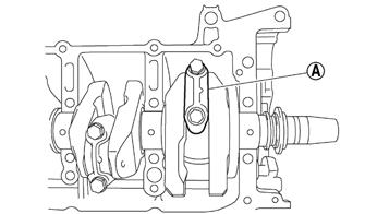
23.Remove the cap screws securing the connecting rod caps (A) to the connecting rods. Account for the bearings.

SNO-760

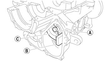
21.Remove the five cap screws securing the oil pump to the crankcase. Account for two dowel pins, one insert, and two O-rings.
SNO-762
NOTE: The indicator mark (A) on the connecting
rod cap will always point to the MAG end of the crankshaft.
SNO-282A
NOTE: Because the connecting rods and connecting
rod caps are unique, note the ID marks and keep all associated parts together for assembling purposes.
24.Remove the crankshaft and piston assemblies from the crankcase.
CAUTION
Pistons can be removed from the top side only.
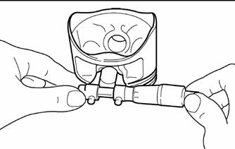
25.Remove the piston pin clips; then remove the piston pin.
SNO-868

NOTE: Before removing the piston pin, de-burr the
piston pin clip groove and the piston pin bore area. If both areas are de-burred and the piston pin is still difficult to remove, remove it with the Piston Pin Puller.
26.Straighten the locking tabs securing the cap screws that secure the balancer shaft; then remove both cap screws and both balancer weights. NOTE: To remove the cap screws (A), place a small
piece of wood (B) between the balancer weight (C) and the crankcase.

SNO-384A
SNO-383A
27.Remove the snap ring securing the water pump drive gear; then remove the gear and shaft and account for a spacer and a bearing.

SNO-319
Servicing Components
Thoroughly clean all non-electrical components in parts-cleaning solvent; then remove any carbon buildup from the cylinder head and piston dome. Visually inspect all engine components for wear or damage. CHECKING CAMSHAFT LOBES
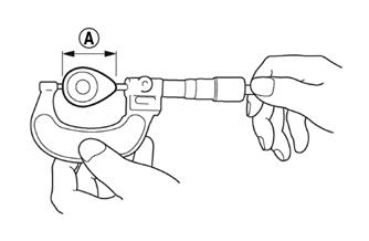
1.Measure the intake camshaft lobe heights (A): 34.350-34.450 mm (1.3523-1.3562 in.). <limit>: 33.650 mm (1.3248 in.). 2.Measure the intake base circle diameter (B): 24.950-25.050 mm (0.9823-0.9862 in.). <limit>: 24.850 mm (0.9783 in.). 3.Measure the exhaust camshaft lobe heights (A): 33.950-34.050 mm (1.3366-1.3405 in.). <limit>: 33.650 mm (1.3248 in.). 4.Measure the exhaust base circle diameter (B): 24.950-25.050 mm (0.9823-0.9862 in.). <limit>: 24.850 mm (0.9783 in.).
CAUTION
If any camshaft lobe is discolored or pitted or if the seating surface is worn, the camshaft must be replaced.
SNO-721
SNO-722
CAUTION

If any camshaft is discolored or pitted or if the seating surface is worn, the camshaft must be replaced.
1.Measure the camshaft runout: 0.030 mm (0.0012 in.).
Replace if necessary.

SNO-723
CHECKING CAMSHAFT JOURNAL-TO- CAMSHAFT CAP Measure the camshaft journal-to-camshaft cap using the following procedure (Clearance — 0.028-0.062 mm (0.0011-0.0024-in.): 1.Install the camshaft into the cylinder head without the dowel pins and the camshaft caps installed. 2.Position a strip of Plastigauge® (A) onto the camshaft journal; then install the dowel pins and the camshaft caps.

SNO-724
3.Tighten the camshaft caps cap screws in stages and in a crisscross pattern working from the inner caps outward. Tighten to 7.2 ft-lb (9.8 N-m). NOTE: Do not turn the camshaft when measuring
the camshaft journal-to-camshaft cap clearance with the Plastigauge®.
4.Remove the camshaft caps and measure the width of the Plastigauge® (B).
SNO-725

CHECKING CAMSHAFT JOURNAL DIAMETER
1.Measure the camshaft journal diameter (A): 24.459-24.472 mm (0.9630-0.9635-in.). Replace if necessary.
SNO-726

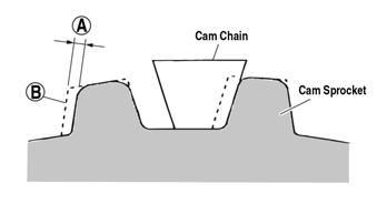
2.If the camshaft is within specification, the cylinder head and camshafts might need to be replaced as a set. CHECKING CAM CHAIN/SPROCKET
1.If the cam sprockets have more than 1/4-tooth of wear (A), the cam sprockets and cam chain should be replaced. (B) indicates new sprocket thickness.
SNO-767

2.If the camshaft is within specification, the cylinder head and camshafts might need to be replaced as a set.
3.If the cam chain or cam sprockets are damaged or wear is found, the cam chain and cam sprockets should be replaced as a set. VALVES
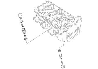
SNO-285
CAUTION
If any valve is discolored or pitted or if the seating surface is worn, the valve must be replaced. Do not attempt to grind a valve or severe engine damage may occur.
If valves, valve guides, or valve seats require servicing or replacement, The manufacturer recommends the components be taken to a qualified machine shop for servicing. 1.Install the drive clutch; then using a Drive Clutch
Spanner Wrench, rotate the engine two full revolutions. 2.Rotate the engine until the camshaft lobe of the valve being measured is directly away from the tappet. 3.Using an appropriate thickness gauge, measure and record the intake and exhaust valve clearance of the cylinder that is on the compression stroke; then rotate the engine 360° and measure and record the valve clearance of the other cylinder. Valve clearance must be within specifications.
15°-25° C (59°-77° F)
Valve Clearance (Cold)
Intake: 0.15-0.22 mm (0.0059-0.0087 in.) Exhaust: 0.21-0.25 mm (0.0083-0.0098 in.)
SNO-672

NOTE: At this point if valve/tappet clearances are
within specifications, servicing is complete. If any valve/tappet clearance is not within specifications, complete step 15 of the Disassembling sub-section before proceeding to step 4.
NOTE: Make a note of the position of each valve
lifter and valve pad so that they can be reinstalled in their original place.
4.To select the correct replacement shim for an out-of-specification clearance, note the three-digit number on the surface of the existing shim; then refer to the appropriate Tappet Shim Selection Table (Exhaust or Intake) in this sub-section and use this procedure:
A.Find the Measured Tappet Clearance (from step 3) in the left-side vertical column of the table.
B.Find the Present Shim Size (three-digit-number) at the top-side horizontal column of the table.
C.Match the clearance in the vertical column with the present shim size to obtain the recommended replacement shim. 5.After verifying proper valve/tappet clearance, install the timing inspection plug to the magneto case and tighten securely. CONNECTING ROD BIG END BEARING NOTE: Do not interchange the big end bearings and
connecting rods. To obtain the correct crankshaft-pin-to-big-end-bearing clearance and prevent engine damage, the big end bearings must be installed in their original positions.
1.Clean the big end bearings, crankshaft pins, and bearing portions of the connecting rods. 2.Install the big end upper bearing into the connecting rod and the big end lower bearing into the connecting rod cap. NOTE: Align the projections on the big end bear-
ings with the notches in the connecting rod and connecting rod cap.


SNO-298
3.Put a piece of Plastigauge® (A) on the crankshaft pin; then install the connecting rod halves.
SNO-854
NOTE: Do not move the connecting rod or crank-
shaft until the clearance measurement has been completed. Apply molybdenum disulfide oil onto the bolt, threads, and seats.
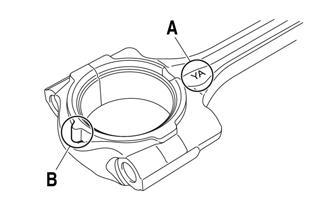
4.Make sure that the “Y” mark (A) on the connecting rod faces toward the right side (AC magneto rotor side) of the crankshaft. 5.Make sure that the characters (B) on both the connecting rod and connecting rod cap are aligned.
SNO-855
6.Tighten the connecting rod cap screws; then remove the connecting rod and big end bearings. Measure the compressed Plastigauge® width (A) on the crankshaft pin.
SNO-659
7.Select the big end bearings (P1-P3).


SNO-660
NOTE: The numbers (A) stamped into the crank-
shaft web and the numbers on the connecting rods are used to determine the replacement big end bearing sizes.

SNO-661
For example, if the connecting rod “P1” and the crankshaft web “P1” numbers are “6” and “2”, respectively, then the bearing size for “P1” is: “P1” (connecting rod) “P1” (crankshaft web) or 6 - 2 = 4 (Green in the bearing color code table below).
BIG END BEARING COLOR CODE 1 Blue 2 Black 3 Brown 4 Green 5 Yellow 6 Pink
CRANKSHAFT JOURNAL BEARING NOTE: Do not interchange the crankshaft journal
bearings. To obtain the correct crankshaft-journal-tocrankshaft-journal-bearing clearance and prevent engine damage, the crankshaft journal bearings must be installed in their original positions.
1.Clean the crankshaft journal bearings, crankshaft journals, and bearing portions of the crankcase. Place the upper crankcase upside down on a bench. 2.Install the journal bearings into the upper engine case. NOTE: Make sure the tabs of the bearings are prop-
erly seated to the notches in the upper engine case.

SNO-684
3.Put a piece of Plastigauge® on each crankshaft journal.

SNO-320A
NOTE: Do not put the Plastigauge® over the oil
hole in the crankshaft journal.
4.Install the crankshaft journal lower bearings into the lower crankcase and assemble the crankcase halves. NOTE: Do not move the crankshaft until the clear-
ance measurement has been completed.
5.Tighten the cap screws in the order of the embossed numbers on the crankcase; then remove the lower crankcase and the crankshaft journal lower bearings. 6.Measure the compressed Plastigauge® width on each crankshaft journal.
SNO-320A
7.If the clearance is out of specification, select replacement crankshaft journal bearings.
NOTE: The numbers stamped into the crankshaft
web and the numbers stamped into the lower crankcase are used to determine the replacement crankshaft journal bearing sizes.
SNO-686

SNO-687

SNO-685
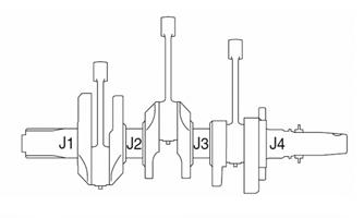
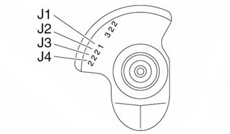
NOTE: “J1 - J4” refer to the bearings shown in the
crankshaft web and lower crankcase illustration. If “J1 - J4” are the same, use the same size for all of the bearings.
For example: if the crankcase “J1” and crankshaft web “J1” numbers are “6” and “1” respectively, the bearing size for “J1” is: J1 (crankcase) - J1 (crankshaft web) + 2 = 6 - 1 + 2 = 7.
CRANKSHAFT JOURNAL BEARING COLOR CODE
2 Black 3 Brown 4 Green 5 Yellow 6 Pink 7 Red 8 White PISTON ASSEMBLY
SNO-862
NOTE: Whenever a piston, rings, or pins are out of
tolerance, they must be replaced.
Cleaning/Inspecting Piston 1.Using a non-metallic carbon removal tool, remove any carbon buildup from the dome of the piston. 2.Inspect the piston for cracks in the piston pin, dome, and skirt areas. 3.Inspect the piston for seizure marks or scuffing. NOTE: If seizure marks or scuffing is detected, the
piston must be replaced.
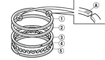
4.Inspect the perimeter of each piston for signs of excessive “blowby.” Excessive “blowby” indicates worn piston rings or an out-of-round cylinder. Removing Piston Rings 1.Starting with the top ring, slide one end of the ring out of the ring groove. 2.Remove each ring by working it toward the dome of the piston while rotating it out of the groove.

SNO-287
NOTE: If the existing rings will not be replaced with
new ones, note the location of each ring for proper installation. When installing new rings, install as a complete set only.
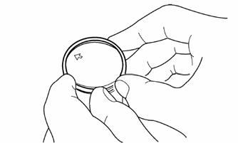
Measuring Piston-Ring End Gap (Installed)
1.Place each piston ring in the wear portion of the cylinder. Use the piston to position each ring squarely in the cylinder. NOTE: Remove any carbon; then clean the top of
the cylinder bore before inserting the piston rings.
2.Using a feeler gauge, measure each piston-ring end gap. Acceptable ring end gap must be within the following specifications.
1st Ring 0.35-0.45 mm (0.014-0.018 in.) 2nd Ring 0.70-0.80 mm (0.028-0.031 in.) Oil Rings 0.10-0.35 mm (0.004-0.014 in.)
1st Ring 0.030-0.065 mm (0.0012-0.0026 in.) 2nd Ring 0.02-0.055 mm (0.0008-0.0022 in.) Cylinder Bore (C) 80.000-80.010 mm (3.150-3.154 in.) Taper Limit (T) 0.050 mm (0.0020 in.) Out of Round (R) 0.050 mm (0.0020 in.)
“C” = maximum of D1 - D6 “T” = maximum of D1 or D2 - maximum of D5 or D6 “R” = maximum of D1 D3 or D5 - maximum of D2, D4, or D6
Piston Ring/Groove Clearance NOTE: Before checking, piston grooves must be
clean, dry, and free of carbon.
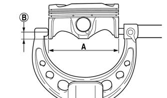
Fit a new piston ring into a piston groove and measure clearance between ring and ringland by using feeler gauge. Measurement must be within the following specifications. If clearance is out of specification, replace piston. 1.Measure the cylinder bore using a gauge by taking side-to-side and front-to-back measurements of the cylinder. Then, find the average of the measurements.
SNO-289
SNO-290
NOTE: If out of specification, replace the crankcase
and the piston and piston rings as a set.
Measuring Piston Skirt Diameter 1.Measure the piston skirt diameter (A) with a micrometer. Be sure to measure 10.0 mm (0.39 in.) from the bottom edge of the piston (B). 2.Piston skirt diameter must be within 79.95-79.96 mm (3.1476-3.1480 in.).
SNO-288
SNO-658A
Measuring Piston Pin Bore Diameter NOTE: It may be necessary to use Piston Pin Puller
to remove the piston pins.
1.Insert an inside dial indicator into the piston-pin bore. Take two measurements to ensure accuracy. 2.Piston pin bore must be within 21.003-21.013 mm (0.8269-0.8273 in.).
SNO-293A
NOTE: Be sure to install the piston rings so that the
manufacturer marks (A) face up.
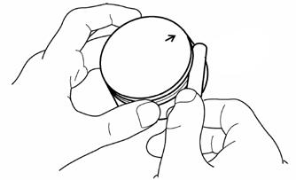
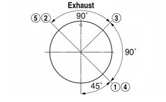
2.Rotate the rings until the ring end gaps are 120° from one another.
SNO-291
Measuring Piston Pin Diameter Measure the piston pin diameter at each end and in the center. Measurement must be within 20.990-20.995 mm (0.8264-0.8266 in.). If measurement is not within specifications, the piston pin must be replaced.
SNO-292

Installing Piston Rings 1.Install the piston rings according to the illustration below. Stagger the end gaps of the upper and lower thin oil rings until they are on directly opposite sides of the piston.
SNO-294A
CAUTION
Incorrect installation of the piston rings will result in engine damage.
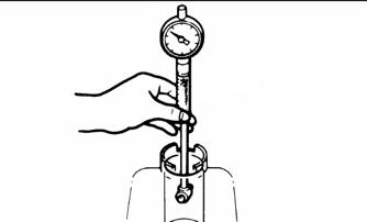
CRANKSHAFT RUNOUT
1.Support the crankshaft using a set of V Blocks; use a dial indicator to read crankshaft runout. NOTE: The contact point of the dial indicator
should be on either side of the oil port hole of the center crankshaft journal and to the outside of the oil port hole on the MAG and PTO end of the crankshaft.
2.Rotate the crankshaft slowly. 3.The reading must be 0.03 mm (0.0012 in.) or crankshaft repairing/replacing will be necessary. MEASURING CRANKSHAFT MAIN/ROD JOURNALS (Bearing Surfaces) 1.Using a micrometer, measure each main and connecting rod bearing journal from along its length and 90° from the first measurement. Measurement must be within 36.976-37.000 mm (1.4557-1.4567 in.) diameter for the crankshaft main journal and 37.976-38.000 mm (1.4951-1.4961 in.) diameter for connecting rod journal.
2.If any journal is badly damaged or has wear that is not within specifications, the crankshaft must be replaced.
Assembling
NOTE: The manufacturer recommends that new
gaskets, seals, and O-rings be installed whenever assembling the engine.
NOTE: For assembling purposes, use oil-dissolvable
molybdenum disulfide grease as engine-assembly grease.
1.Install the balancer driven gear (A); then install the balancer shaft (B) making sure to face the punch mark (C) on the balancer driven gear inward. Align the projection (D) on the balancer shaft with the slot (E) in the balancer driven shaft.


SNO-385A
2.Install the water pump drive gear (A) by aligning the punch mark (B) on the water pump gear with the shorter spline (C) on the balancer shaft end.
SNO-386A

3.Install the right balancer weight (A) onto the shaft; then install the washers, lock washers, and secure using the existing cap screws making sure to align the punch mark (B) on the shaft with the shorter spline (C) on the shaft end.

SNO-387A
4.Install the left balancer weight (A) onto the shaft; then install the washers, lock washers, and secure using the existing cap screws making sure to align the punch mark (B) on the shaft with the shorter spline (C) on the shaft end.
SNO-388A
5.Secure the balancer weights (C) using a small piece of wood (B). Tighten cap screws to 25 ft-lb (34 N-m); then bend the locking washer over the cap screw (A).
SNO-384A
SNO-383A
6. Apply engine oil onto the piston pin. Make sure the
“Y” mark (A) on the connecting rod faces to the
MAG side when the punch mark (B) on the piston is pointing up.
SNO-295A

7.Install the piston pin clips so the clip ends are 3 mm (0.12 in) (C) or more from the cutout in the piston.
Make sure the oil ring end gaps are on directly opposite sides of the piston and the compression ring end gaps are 90° from one another.
SNO-297
9.Rotate the engine to the upside down position for installing the crankshaft. 10.With the proper bearings selected, install the half-bearings into the upper engine case; then lubricate the bearing faces liberally with engine-assembling grease taking care not to get any grease between the engine case and bearing. NOTE: Make sure the tabs of the bearings are prop-
erly seated to the notches in the upper engine case.
SNO-298
11.Install the output shaft onto the crankcase making sure to align the shallow groove (A) with the low spline (B) of the crankshaft.

SNO-296

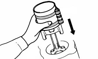
8.With the piston rings installed, lubricate each piston and cylinder with engine oil; then with the punch marks on the top of the pistons directed toward the exhaust side of the engine, install the piston assemblies into the cylinder using Ring Compressor and a soft hammer.
SNO-856
NOTE: When installing the crankshaft assembly
(A), make sure to align the punch mark (B) of the balancer drive gear (C) on the crankshaft with the punch mark (D) of the balancer driven gear (E).
SNO-440A
12.Align the hole (A) in the bearing with the pin (B) on the upper crankcase; then install the crankshaft.

SNO-857
NOTE: Make sure the “Y” marks (A) on the con-
necting rods face toward the right side (MAG side) of the crankshaft. Make sure the projection (B) faces toward the right side (MAG side) of the crankshaft.
SNO-858
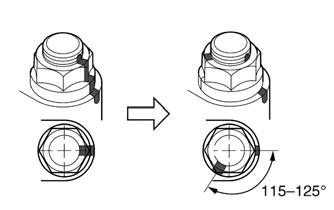
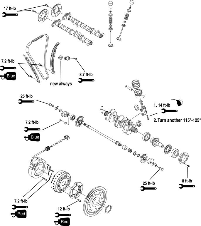
13.Seat the connecting rods to the crankshaft; then install the connecting rod caps, new cap screws, and new nuts. Tighten only until snug at this time. 14.Alternately tighten each of the connecting rod cap screws evenly to 14 ft-lb (19 N-m); then put a mark (A) on each connecting rod cap screw. Tighten the connecting rod cap screw further to reach the specified angle (115°-125°).

SNO-859
NOTE: Rotate the crankshaft one revolution to ver-
ify free movement.
15.Using Three Bond Sealant, apply a light film of sealant onto the sealing surfaces of the upper and lower engine cases.

SNO-301
NOTE: Do not allow any sealant to come into con-
tact with the oil galley or crankshaft journal bearings. Do not apply sealant to within 2-3 mm (0.08-0.12 in.) of the crankshaft journal bearings.
16.Install the lower crankcase half to the upper engine case; then verify the cases are properly seated together. 17.Install the cap screws into the proper locations in the crankcase; then with the torque pattern shown as numbered on the case, tighten the cap screws only until snug.

SNO-302
NOTE: Lubricate the threads and washers of cap
screws 1-8 with engine oil. Lubricate bolts 9-15, the threads of 19-24 and the mating surface with engine oil. Apply Three Bond Sealant to the threads of cap screws 16-18.
18.Tighten crankcase cap screws 1-8 to 11 ft-lb (15 N-m); then loosen and re-tighten to 11 ft-lb (15 N-m). 19.Tighten the cap screws 1-4 an additional 95°-100°; then tighten cap screws 5-8 an additional 75°-80°.

SNO-303
NOTE: If a cap screw is tightened more than the
specified angle, do not loosen the bolt and then re-tighten it. Instead, replace the bolt with a new one and perform the procedure again.
NOTE: Do not use a torque wrench to tighten the
bolt to the specified angle.
20.Tighten cap screws 9-24 in order of the embossed numbers on the crankcase. Tighten cap screws 9-12 to 17 ft-lb (23.1 N-m) and cap screws 13-24 to 8.7 ft-lb (11.8 N-m).
SNO-304
NOTE: After the tightening sequence, rotate the
crankshaft one revolution to verify free movement.
21.Make sure the dowel pins, insert, and the two
O-rings are in place; then position the oil pump assembly on the crankcase and secure using the existing cap screws. Tighten to 8.7 ft-lb (11.8 N-m).
YM-020A
NOTE: At this time, install the timing chain around
the crankshaft as it must go on before the oil pump chain.
22.Position the oil pump chain around the crankshaft; then install the oil pump driven gear and secure using the existing cap screw. Tighten to 11 ft-lb (15 N-m).

YM-019
NOTE: Install the oil pump driven gear with the
stamped mark “4XV” facing toward the oil pump assembly.

SNO-305
23.Position the oil pump chain guide with the existing mounting locations and secure using the existing cap screws. Tighten to 7.2 ft-lb (9.8 N-m). 24.With a new gasket and the existing dowel pins in place, install the oil pan and install the different-length cap screws. Using the pattern shown, tighten the screws to 86 in.-lb (9.7 N-m).

SNO-306
NOTE: If the oil pan drain plug was removed,
always install new plug washer and reservoir O-ring.
NOTE: At this time, rotate the engine to the upright
position.
NOTE: Prior to installing the cam chain tensioner,
ensure the chain is properly seated to the gear on the crankshaft.
25.Install the chain guides and secure using the existing cap screws (threads coated with blue Loctite #243).
Tighten to 86 in.-lb (9.7 N-m). NOTE: Clean the tapered portion of the crankshaft
and the flywheel.
26.With the key installed into the crankshaft, install the flywheel onto the crankshaft aligning with the key on the crankshaft until it is fully seated. Using a rubber hammer, tap the rotor onto the crankshaft. 27.Apply Three Bond Sealant to the stator grommet; then place the grommet into the crankcase groove.

SNO-625
28.Install the magneto cover and secure using the existing Allen-head screws. Tighten to 8.7 ft-lb (11.8 N-m). 29.Position the alternator output assembly with the magneto cover; then thread the lip seal into the cover. Using a 41 mm crowfoot wrench, tighten the lip seal to 60 in.-lb (6.8 N-m).
XX315
30.Tighten the alternator output black cap screw to 70 ft-lb (95.2 N-m). 31.Position a new cylinder head gasket onto the crankcase; then position the existing dowel pins into the cylinder. 32.Route the timing chain through the cylinder head assembly and place the head onto the crankcase. NOTE: Make sure to use new cap screws 3-10 when
installing the head.
33.Lubricate the cap screws 3-10; then secure the cylinder head assembly to the crankcase using the existing cap screws. Tighten to 18 ft-lb (24.5 N-m); then loosen the cap screws and re-tighten to 18 ft-lb (24.5 N-m).
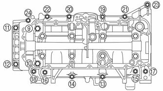
SNO-280

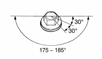
34.Tighten the cylinder head bolts further to reach the specified angle 175°-185° in the proper tightening sequence as shown. Do not use a torque wrench for this step.

SNO-308
35.Tighten the Allen-head screws 1 and 2 to 8.7 ft-lb (11.8 N-m). 36.Lubricate the camshaft bearing surfaces and lobes with engine oil, then position the intake and exhaust camshaft assemblies into the head. 37.Turn the crankshaft clockwise. Align the “I” mark (A) on the magneto rotor with the stationary pointer (B) on the magneto cover. This will position cylinder 3 piston to TDC.
SNO-279A
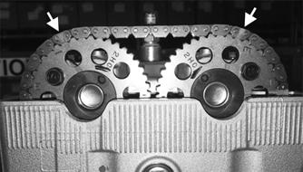
38.Install the camshafts with the hole (C) in cylinder #3 (cam facing up). When installing the timing chain, start with the intake camshaft and be sure to keep the timing chain as tight as possible on the intake side.
Make sure the marks (D) on the timing chain sprockets are parallel with the edge of the cylinder head.
Location (E) is cylinder #3 cam lobe location for each camshaft.

SNO-622A
SNO-311A
NOTE: Secure the chain to the sprockets using two
cable ties in the areas shown below. This will prevent the chain from jumping a tooth while the chain tensioner is being installed.
XX182
39.Install the existing dowel pins into the cylinder head; then install the intake and exhaust camshaft caps.
Tighten the camshaft cap screws to 86 in.-lb (9.7 N-m) in two stages and in a crisscross pattern working from the inner caps out.

NOTE: The “I” mark refers to the intake camshaft
caps and the “E” mark refers to the exhaust camshaft caps. Install the camshaft caps with the arrow mark (A) pointing toward the MAG side of the engine. Make sure the holes (B) in the camshaft are aligned with the marks (C) on the camshaft caps.
NOTE: Insert the timing chain tensioner rod little
by little so that the circlip (A) comes into the groove in the rod (B). Check that the mark (C) on the timing chain tensioner housing is aligned with the timing chain tensioner clip (D) and that the timing chain tensioner rod is locked in position.

A
D B
C B
SNO-623A
CAUTION
Lubricate the camshaft cap screws with engine oil. The camshaft cap screws must be tightened evenly or damage to the cylinder head, camshaft caps, and camshafts will result. Do not turn the crankshaft when installing the camshaft to avoid damage or improper valve timing.
40.Slowly insert the timing chain tensioner rod (A) into the timing chain tensioner housing while squeezing the timing chain tensioner clip (B) until the clip is in the groove.
SNO-626A
41.Insert the timing chain tensioner rod little by little so that the circlip (A) is seated into the groove (B).

SNO-628A
42.Install the chain tensioner assembly and secure using the existing Allen-head screws. Tighten to 8.7 ft-lb (11.8 N-m). NOTE: Be sure to install the timing chain tensioner
gasket so its section with the “L” mark is protruding from the lower left side of the timing chain tensioner. The arrow mark (A) on the timing chain tensioner should face up.

SNO-315A
43.Remove the cable ties securing the chain to the sprockets. 44.Tighten the cylinder head cover screws in a crisscross pattern to 8.7 ft-lb (11.8 N-m).
VOR-518
45.Install the spark plugs. Tighten to 9.4 ft-lb (12.8 N-m).
Install the ignition coils over the spark plugs making sure they are fully seated. Secure using existing cap screws. Tighten to 8 ft-lb (10.9 N-m).
VOR-519
Assembly Schematic
Torque Specification Tolerances Couple Tolerance
N-m ft-lb
0-20.3 0-15 ±20% 21.7-52.9 16-39 ±15% 54.2+ 40+ ±10%

XX998cc_18_1
Troubleshooting Engine
Problem: Engine Does Not Start (No Spark at Spark Plugs) Condition Remedy
1. Ground connections dirty — loose 1.Check all ground connections — clean and tight 2. Wiring harness shorting — disconnected 2.Repair — replace — connect wiring harness 3. Spark plugs fouled — damaged 3.Clean — replace spark plugs 4. ECM faulty 4.Replace ECM 5. Ignition timing sensor faulty 5.Replace sensor
Problem: Engine Does Not Start (No Fuel at Cylinders) Condition Remedy
1. Gas tank empty 1.Fill tank 2. Gasoline contaminated 2.Replace gasoline 3. Fuel pump faulty 3.Service — replace fuel pump — connections — wires 4. Fuel hose broken — pinched 4.Replace — service hose 5. Gas-tank vent hose obstructed 5.Remove obstruction — replace vent — hose 6. Pick-up valve(s) obstructed — damaged 6.Remove obstruction — replace pick-up valve(s) 7. Compression absent 7.Repair — replace damaged — worn engine components 8. ECM faulty 8.Replace ECM
Problem: Engine Does Not Start (Fuel Does Not Ignite) Condition Remedy
1. ECM Check Engine light failed 1.Check codes — repair as necessary 2. Spark absent 2.Check for spark — see No Spark at Spark Plugs sub-section 3. Compression low 3.Service engine 4. Engine flooded 4.Clear engine (hold throttle full-open) 5. Gasoline contaminated 5.Clean tank and entire fuel system
Problem: Engine Does Not Idle Condition Remedy
1. ECM trouble code 1.Service — replace problem component 2. Injector(s) faulty 2.Replace injector(s) 3. Fuel pressure regulator faulty 3.Replace regulator — hose 4. Air filter obstructed 4.Replace air filter
Problem: Engine Loses Power Condition Remedy
1. Sensor faulty 1.Check the Check Engine light for trouble code — repair — replace problem circuit or sensor 2. Spark plug fouled 2.Replace spark plugs 3. External coil faulty 3.Service — replace coil 4. Gas tank vent hose obstructed 4.Service — replace vent hose 5. Compression low 5.Service engine 6. ECM faulty 6.Replace ECM 7. Fuel pressure regulator faulty 7.Replace regulator 8. Check Engine light illuminated 8.Check codes — repair as necessary 9. Injector faulty 9.Replace injector
Problem: Engine Overheats Condition Remedy
1. Coolant low — absent 1.Add coolant 2. Radiator obstructed 2.Remove obstructions 3. Drive system (primary sheave — secondary sheave — 3.Troubleshoot — adjust drive system track — drive belt) adjusted incorrectly — worn 4. Rings/grooves carboned 4.Clean — replace rings — pistons 5. Exhaust obstructed 5.Remove obstruction 6. Compression low — absent 6.Repair — replace damaged — worn engine components 7. Water pump — thermostat damaged — faulty 7.Replace water pump — thermostat
Problem: Engine Backfires Condition Remedy
1. Check Engine light illuminated 1.Check codes — replace problem component 2. Spark plugs fouled — damaged 2.Clean — replace spark plugs
Problem: Engine Stops Suddenly Condition Remedy
1. Gas tank empty 1.Fill tank 2. Spark absent 2.See No Spark at Spark Plugs subsection 3. Check Engine light illuminated 3.Check codes — replace problem component 4. Fuel pressure low 4.Replace regulator — hose 5. Fuel pump faulty 5.Service — replace fuel pump 6. Fuel pump relay faulty 6.Replace relay 7. Gas tank vent hose obstructed 7.Service vent hose 8. ECM faulty 8.Replace ECM 9. Fuel hose obstructed — broken — pinched 9.Remove obstruction — repair — replace fuel hose 10. Ignition coil faulty 10.Replace ignition coil 11. Engine seized 11.Overhaul engine 12. Oil pressure low 12.Check oil level/engine 13. Engine coolant temperature above normal 13.Inspect cooling system
Servicing Clutch Components
NOTE: The engine does not have to be removed
from the frame for this procedure.
SPECIAL TOOLS A number of special tools must be available to the technician when performing service procedures in this section. Refer to the current Special Tools Catalog for the appropriate tool description. NOTE: When indicated for use, each special tool
will be identified by its specific name, as shown in the chart below, and capitalized.
Description p/n
Belt Removal Tool (provided in tool kit) 0744-098 Drive Clutch Puller 0744-080 Drive Clutch Spanner Wrench 0644-136 Driven Clutch Compressor Tool Common Tool Clutch Retention Tool — XX 0444-321 Clutch Alignment Bar 0644-651
NOTE: Special tools are available from the Service
Department.
Removing Clutch Components NOTE: If removing the drive clutch, removal of the
shock absorber is required by raising the rear of the vehicle just enough to unload the rear suspension (weight off the shock absorber); then removing the shock absorber fasteners.
2.Unlatch the retaining clips securing the CVT cover.
VOR-506
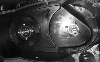
3.Remove the CVT cover. When removing CVT cover, disconnect it from the front cooling duct. 4.Install the Belt Removal Tool turning clockwise into the driven clutch. Remove the drive belt starting from the bottom of the driven clutch.
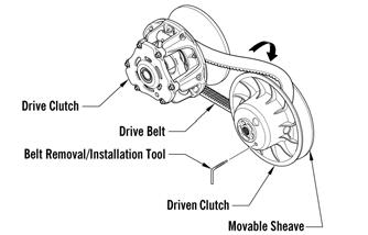
5.Remove the cap screw with the Drive Clutch Bolt
Tool and Drive Clutch Spanner Wrench by turning counterclockwise securing the drive clutch assembly; then use the Drive Clutch Puller and the Drive
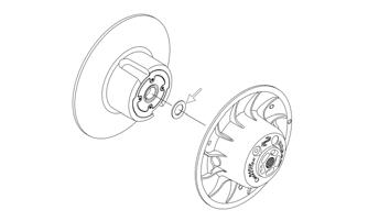
Clutch Spanner Wrench to remove the drive clutch. 6.Remove the cap screw and washer that secure the driven clutch assembly to the shaft.
XX145

7.Slide the stationary and movable sheaves off the driven shaft. Account for the shim(s).

SNO-547
DRIVE CLUTCH Disassembling NOTE: Note the timing marks on the cover, spider,
and movable sheave. These must be aligned when assembling the drive clutch for balance purposes.
1.Remove the three cap screws and nuts securing the fan to the clutch. 2.Loosen the machine screws securing the cover.
Remove every other cap screw and lock washer from the cover; then while firmly holding the cover and movable sheave together, remove the three remaining screws equally. 3.Remove the cover and spring.
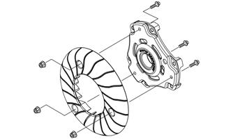

VOR-509
4.Remove the shoulder screw and lock nut securing the cam arm.
VOR-510
Cleaning and Inspecting 1.Using parts-cleaning solvent, wash grease, dirt, and foreign matter off all components; dry with compressed air.
! WARNING
Always wear safety glasses when using compressed air to dry components.
2.Remove any drive belt dust accumulation from the stationary sheave, movable sheave, and bushings using parts-cleaning solvent only. 3.Inspect stationary sheave, movable sheave, spider, and cover for cracks or imperfections in the casting. 4.Inspect the shoulder screws for wear or bends. 5. Inspect the spring for distortion, cracks, or wear. 6.Inspect rollers for damage or wear. Assembling NOTE: The drive clutch rotates counterclockwise
and the shoulder screw should be installed in the direction of rotation.
1.With the cam arm pin properly positioned between the clutch towers, install the shoulder screw through the clutch and the cam arm. Secure using new lock nut. Tighten to 50 in.-lb (5.6 N-m).
VOR-510
CAUTION
Care must be taken when installing the cover not to damage the bushing.
2.Place the spring and cover into position making sure the timing mark (X) on the cover is properly aligned with the spider and the movable sheave; then compress the spring and install the screws. In a crisscross pattern, tighten evenly to 120 in.-lb (13.6 N-m).
VOR-508
DRIVEN CLUTCH Disassembling 1.Place the movable sheave on the Driven Clutch
Compressor Tool with the torque bracket facing up; then install the compressor flange and handle against the torque bracket.
2.Apply heat to the screws securing the torque bracket to the movable sheave; then remove the screws.
CAUTION
Do not allow the compressor tool to touch either of the driven clutch bushings as it may cause damage.

VOR-509
CAUTION
Cap screws securing the fan to drive clutch must be installed in the correct direction or clutch damage will occur.
3.Install the three cap screws from the sheave side of the drive clutch; install the lock nuts on the fan side securing the fan to the clutch. Tighten to 60 in.-lb (6.8 N-m).
XM342
3.Release the compression of the spring by removing the wing nut; then remove the torque bracket, spider assembly, and the driven clutch spring.

XM344
Cleaning and Inspecting 1.Using parts-cleaning solvent, wash grease, drive belt dust, and foreign matter off all components.
2.Inspect the rollers and spider for damage, cracks, or wear. 3.Inspect the sheaves for any gouges, cracks, or other damage. Also, inspect threaded areas of sheaves for damaged or stripped threads. 4.Inspect the torque bracket for cracks or damage. The ramp portions of the bracket must be free of gouges and damage. 5.Inspect spring for distortion, crystallization, or breaks. 6.Inspect the torque bracket and movable sheave bearing for wear. If wear is present, replace the bracket or sheave. Replacing Rollers 1.With the torque bracket removed from the movable sheave, remove the driven spider assembly from the torque bracket. 2.Remove the retaining rings and thrust washers securing the rollers on the spider.
CAUTION
Do not use steel wool or a wire brush to clean driven components. A wire brush or steel wool will cause the sheaves to be gouged (thus, the drive belt may not slide between sheaves). Decreased performance and possible accelerated drive belt wear will result.
XM383

3.Place a new roller into position and secure with the existing thrust washers and retaining rings. Make sure the rounded side of the bore is installed toward the inside or the retaining ring will not seat into the groove of the spider shaft. Assembling 1.Place the movable sheave onto the Driven Clutch
Compressor Tool; then install the spring into the sheave making sure the tab is placed.
XM384
2.Install the spider assembly over the spring; then position the torque bracket over the spider and install the compressor flange spacer and wing nut; then compress the torque bracket over the spider and install the compressor flange spacer and wing nut; then compress the torque bracket until the mounting locations align.
XM344
3.Secure the torque bracket using new screws. Tighten in a crisscross pattern to 120 in.-lb (13.6 N-m).

XM347
4.Remove the clutch from the compressor. Installing Clutch Components 1.Place the movable driven sheave onto the driveshaft.
Install the shim(s). Install the stationary sheave.
Install the cap screw and washer making sure the washer is cupped toward the sheave. Holding the driven clutch with the Clutch Retention Tool, tighten the bolt to 60 ft-lb (81.3 N-m).
SNO-547
NOTE: Before installing the drive clutch, be sure to
wipe both the crankshaft taper and clutch mounting taper clean using a clean towel.
2.Place the drive clutch into position on the crankshaft.
CAUTION
When installing the drive clutch, do not tighten the cap screw with any kind of impact tool. Tighten cap screw using a hand torque wrench only. Failure to do so could result in stationary sheave damage.
3.Using the Drive Clutch Spanner Wrench and Drive
Clutch Bolt Tool, secure using the cap screw and high collar washer. Tighten to 60 ft-lb (81.3 N-m). 4.Install the Belt Removal Tool turning clockwise into the driven clutch. Install the drive belt starting from the bottom of the driven clutch. Remove the Belt
Removal Tool.
SNO-778
5.Making sure the clutch cover gasket stays within the channel along the whole CVT cover housing, install the CVT cover starting from the rear of the vehicle. 6.Latch the clamps securing the CVT cover. 7.Connect the cooling duct to the CVT cover; install and tighten the clamp securing the cooling duct to the CVT cover.
VOR-506
8.If the shock absorber was removed, install the rear shock absorber and secure with the cap screws.
Tighten the upper cap screw to the recommended torque and the lower cap screw to the recommended torque. Checking Clutch Offset Shims for adjusting offset:
1.Loosen the clamp securing the cooling duct to the
CVT cover. 2.Unlatch the retaining clips securing the CVT cover.
Part Number
0648-849 0648-912 0648-850
Shim Thickness
0.030 (0.76 mm) 0.060 (1.52 mm) 0.090 (2.29 mm)
VOR-506
3.Remove the CVT cover. When removing CVT cover, disconnect from the front cooling duct. 4.Install the Belt Removal Tool turning clockwise into the driven clutch. Remove the drive belt starting from the bottom of the driven clutch. Remove the
Belt Removal Tool 5.Using the Clutch Retention Tool to secure the driven clutch, remove the cap screw and washer that secure the driven clutch assembly to the shaft.
XX145
6.Slide the stationary off and verify only a 0.090” (2.29 mm) thickness shim is installed. If size is not a 0.090” (2.29 mm) thickness shim, install only a 0.090” (2.29 mm) thickness shim.
SNO-547A
7.Using the Clutch Retention Tool to secure the driven clutch, install the cap screw and washer making sure the washer is cupped toward the sheave to secure the driven clutch assembly to the shaft. Torque to 60 ft-lb (81.6 N-m).
XX145
8.Position the Clutch Alignment Bar onto the driven clutch making sure the Clutch Alignment Bar does not touch the fins on the driven clutch. The Clutch
Alignment Bar should only contact the outer portions of the driven clutch as indicated.

XX456
9.While holding the Clutch Alignment Bar against the driven clutch as indicated in step 8, position the other end of the Clutch Alignment Bar above the drive clutch stationary sheave. Gently rotate the driven clutch counterclockwise while holding the Clutch
Alignment Bar against the driven clutch. The Clutch
Alignment Bar should not get pushed out by the drive clutch stationary sheave. If the Clutch Alignment Bar does get pushed out by the drive clutch stationary sheave, add shims as needed.
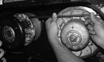
XX457
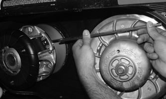
XX458
10.Install the Belt Removal Tool turning clockwise into the driven clutch. Install the drive belt starting from the bottom of the driven clutch. Remove the Belt
Removal Tool.
SNO-778
11.Making sure the clutch cover gasket stays within the channel along the whole CVT cover housing, install the CVT cover starting from the rear of the vehicle. 12.Latch the clamps securing the CVT cover. 13.Connect the cooling duct to the CVT cover; install and tighten the clamp securing the cooling duct to the CVT cover.