18 minute read
Suspension

The following suspension system components should be inspected periodically to ensure proper operation: A.Shock absorber rods bent, pitted, or damaged. B.Reservoirs damp or leaking. C.Shock absorber body damaged, punctured, or leaking. D.Shock absorber eyelets broken, bent, or cracked. E.Shock absorber eyelet bushings worn, deteriorated, cracked, or missing.
F.Shock absorber spring broken or sagging. G.Sway bar mountings tight and bushings secure. H.Proper preload and damping for conditions.
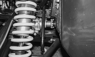
Shock Absorbers
CHECKING/ADJUSTING RIDE HEIGHT ! WARNING
Always ensure the vehicle is adjusted to the specified ride height. Failure to do so can result in adverse changes to the vehicle’s ride and handling, which could cause accidents or overturns.
NOTE: The preload collars MUST maintain contact
with the spring at all times. Do not remove so much preload that the collar loses contact with the spring and allows the spring to “float” between the upper and lower spring collars.
NOTE: Ensure the vehicle is on level ground, the
tires are properly inflated to 14 psi (96.5 kPa) for the front tires and 22 psi (151.7 kPa) for the rear tires. This is for an average operating load in the vehicle.
NOTE: Before attempting to adjust the suspension,
clean dirt and debris from the sleeve and remove load from the suspension by using a jack to lift the frame and allow the shock to fully extend. Loosen each preload lock adjustment ring; then use an appropriate spanner wrench to adjust the preload adjustment ring to the desired position.
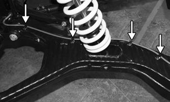
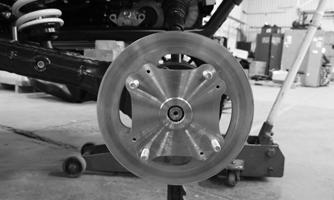
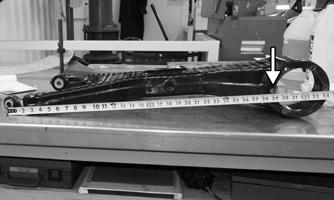
1.Measure from the ground to the bottom of the frame tube in the locations shown behind the front lower
A-arms. Measurement should be 14 in. (35.6 cm).
XX258
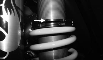
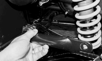
2.If measurement is not as specified, use a jack positioned under the front of the frame to lift and fully extend the front shocks. With a spanner wrench, loosen the preload lock adjustment ring located above the preload adjustment ring; then use an appropriate spanner wrench to rotate the preload adjustment ring in the desired directions shown.
Adjust the left- and right-side springs equally as required. Tightening the springs will increase ground clearance, loosening the springs will decrease ground clearance. Secure the preload lock adjustment ring when correct ride height is achieved.
XX130

XX130A
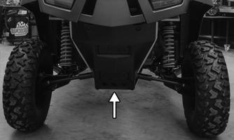
3.On the rear, measure the ground to the bottom of the skid plate. Measurement should be 14 in. (35.6 cm).
XX257
4.If measurement is not as specified, use a jack positioned under the rear of the frame to lift and fully extend the rear shocks. With a spanner wrench, loosen the preload lock adjustment ring located above the preload adjustment ring; then use an appropriate spanner wrench to rotate the preload adjustment ring in the desired directions shown.
Adjust the left- and right-side springs equally as required. Tightening the springs will increase ground clearance, loosening the springs will decrease ground clearance. Secure the preload lock adjustment ring when the correct ride height is achieved.
CAUTION
The shocks are factory filled with high pressure gas. Do not remove the Schrader valves or gas leakage will occur damaging the shock.
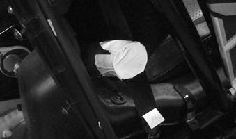
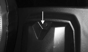
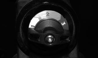
COMPRESSION DAMPING ADJUSTMENT To adjust damping, rotate the knob located at the top of each shock reservoir in the desired direction (firmer or softer). Ensure adjustments made are equal left to right on the front shocks and on the rear shocks. NOTE: There are 3 positions of compression damp-
ing adjustment: Position 1 is softest, Position 2 is medium, Position 3 is firm.
XX131
NOTE: Suspension settings from the factory are
optimally set for a wide variety of riding conditions. However, if additional adjustments are necessary always make your adjustments in small increments until the desired ride is achieved. Be sure to also record your adjustments for future reference.
CAUTION
Continuous high speed operation of this vehicle with excessive spring preload (suspension maintained at full extension) may result in CV boot damage.
REMOVING
1.Secure the vehicle on a support stand to elevate the wheels and to release load on the suspension. 2.Remove the two cap screws and nuts securing each shock absorber to the frame and A-arms. Account for the spacers and O-rings from each.
Front A-Arms
REMOVING UPPER
1.Lift and support the vehicle with a support stand to allow access to the front suspension. 2.Remove the front wheels. NOTE: If the technician’s objective is only to
remove the A-arms, proceed to step 6.
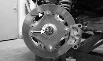
3.Remove the lock plate and hub nut securing the hub.
XX183
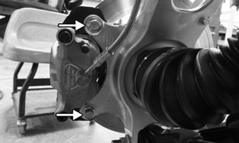
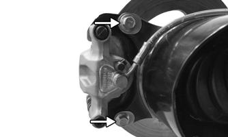
4.Remove and discard the “patch-lock” cap screws securing the brake caliper to the hub.
XX184
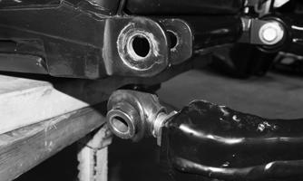
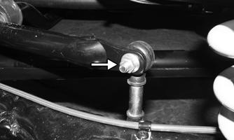
5.Remove the cap screw and nut securing the tie rod end to the knuckle; then remove the tie rod end from the knuckle.

XX185
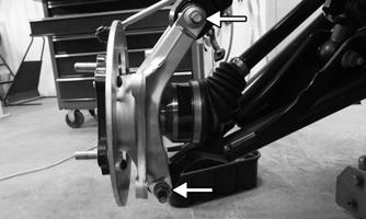
6.Remove the cap screws and nuts securing the knuckle to the upper and lower A-arms.
XX186
CAUTION
Support the knuckle when removing the cap screws to prevent damage.
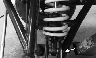
7.Remove the cap screw and nut securing the lower shock eyelet to the A-arm. Remove the shock from the A-arm.
XX187
8.Remove the brakeline hose routing clips from the upper A-arm (B); then remove the cable tie that secures the brakeline to the A-arm (A).

XX188
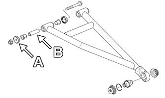
9.Account for the bushing (B) and the seals (A) on the
A-arm mount.
XX189
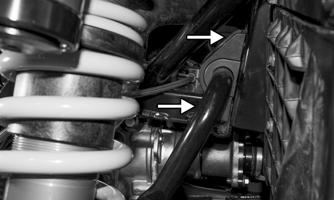
10.Remove the two cap screws that secure the upper
A-arm to the chassis (A). It may be necessary to remove the P-clamp (B) to allow enough room for the front cap screw to be removed.

XX190
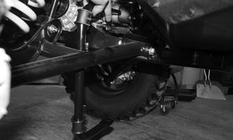
REMOVING LOWER
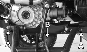
1.Remove the cap screw and discard the lock nuts securing the lower A-arm to the frame (A). Remove the A-arm. 2.Remove the cap screw that secures the sway bar link to the lower A-arm (B). Remove the A-arm.
XX193
3.Account for the bushing (B) and the seals (A) on the
A-arm mount.

XX194
CLEANING AND INSPECTING
1.Clean all of the A-arm components in a parts-cleaning solvent. 2.Inspect the A-arms for bends, cracks, and worn bushings. 3.Inspect the frame mounts for signs of damage, wear, or weldment damage. INSTALLING NOTE: This process is the same for the upper and
lower A-arm.
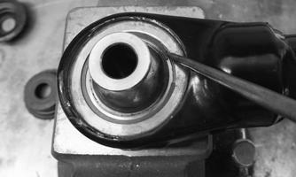
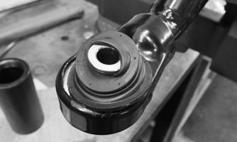
1.To remove the bearing, remove the boot by prying on the edge. Repeat this process on the opposite side.

XX241 XX191
3.Remove the bearing with a suitable press. 4.Press a new bearing into place, and secure with the
C-clip. NOTE: Remove the ball joint only if replacement is
necessary.
5.Inspect the boot for damage. Slide the boot over the end of the bearing.
XX195
6.Using a suitable size socket or similar tool, evenly drive the edge of the boot into the A-arm. Repeat this process for the opposite side.

XX192
7.Install the lower A-arm into the frame mounts and secure it with the cap screw and new lock nut (A).
Tighten to 75 ft-lb (102 N-m). 8.Install the sway bar link to the A-arm (B). Tighten to 35 ft-lb (48 N-m).
XX193
9.Using a new “patch-lock” cap screw, secure the shock to the lower A-arm. Tighten to 75 ft-lb (102 N-m). 10.Remove the cap screw and nut securing the lower shock eyelet to the A-arm. Remove the shock from the A-arm.
XX187
11.Install the upper A-arm to the frame with the cap screw and new lock nut (A). Tighten to 75 ft-lb (102 N-m). Install the P-clamp (B).
XX190
12.If a new wheel bearing is needed, it can be replaced by removing the snap ring and pressing the old bearing out using a suitable press. Press the new bearing in place and secure with the snap ring.

XX196
13.Install the knuckle on the lower ball joint using the existing cap screw and a new nut. Finger-tighten only at this time. With the axle going through the center of the knuckle, rotate it upward and secure the upper A-arm to the knuckle using the existing cap screw and a new nut. Tighten both cap screws to 75 ft-lb (102 N-m).

XX197
14.Install the tie rod end using the existing cap screw and a new nut. Tighten to 42 ft-lb (57 N-m).
XX185
15.Install the hub and axle nut. Apply red Loctite #271 to the axle nut and tighten to 250 lb-ft (339 N-m).
Continue to tighten until the locking plate fits over the nut.

XX198
16.Using new “patch-lock” cap screws, secure the brake caliper to the brake disc. Tighten to 35 ft-lb (48 N-m).
XX184
17.Route the brakeline hose along the upper A-arm and secure it with the clips (B) and a cable tie (A).
Tighten the clips to 6 ft.-lb (8 N-m).
XX188
18.Install the wheels and using a crisscross pattern, tighten the wheel nuts in 20 ft-lb (27 N-m) increments to a final torque of 95 ft-lb (129 N-m). 19. Remove the vehicle from the support stand.
Rear Trailing Arms
REMOVING
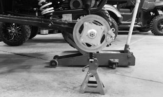
1.Lift and support the vehicle on a support stand that allows access to the rear suspension with the rear tires off the floor. Remove the wheel(s). CAUTION
Support the trailing arm to prevent it from going past the full drop position when the axle is in place. If the axle is in place and the trailing arm falls below full drop, damage to the axle will occur.
XX203
3.Remove and discard the “patch-lock” cap screws securing the brake caliper to the hub.
X199
4.Remove the cap screws securing the brakeline hose to the trailing arm. Set the brake caliper aside.
XX200
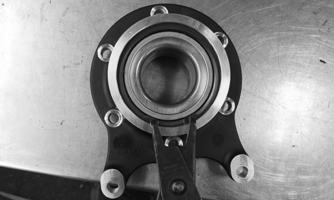
5.Remove the locking plate and hub nut securing the hub.
XX204
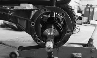
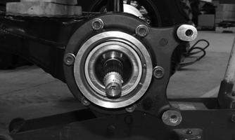
6.The hub and bearing housing assembly may be removed. Doing so will prevent damage to the axle.
XX206
7.With the trailing arm still supported, remove the cap screws securing the shock to the frame and trailing arm. Discard the lock nuts.

XX201 XX208


9.Remove the cap screws securing the trailing arm to the frame. Remove the trailing arm.
Lower
XX209
NOTE: The drive axle does not need to be removed
for this procedure.
CLEANING AND INSPECTING
1.Clean all components. 2.Inspect the trailing arm for bends, cracks, worn bushings, and worn bearings. 3.Inspect the frame mounts for signs of damage, wear, or weldment damage. INSTALLING
1.Apply a light amount of grease on the shock mount sleeve and insert it into the trailing arm.

2.Press the spherical bearing into the trailing arm and secure it with a snap ring. NOTE: This bearing may already be installed in the
trailing arm. This bearing is not reusable.

XX211
3.Install the rod end with the lock nut into the trailing arm. Do not tighten the jam nut.
XX212
4.Take a preliminary measurement from the center of the rod end to the center of the front mount hole for the bearing assembly. Adjust the rod end to obtain the correct distance of 28.75 in. (73 cm). There is approximately 1/16 in. (1.6 mm) of movement per turn of the rod end. Do not tighten the jam nut.
XX213
5.Install the inner trailing arm mount to the frame.
Torque the nut to 170 lb-ft (230 N-m). Install rod end mounting cap screw but do not install the nut.

XX214
6.Install the shock absorber into the trailing arm mount and tighten to 65 lb-ft (88 N-m). Install the shock absorber into the chassis mount and torque the nut to 65 lb-ft (88 N-m). 7.Ensure the axle is in place.

XX215
8.If a new wheel bearing is needed, it can be replace by removing the snap ring and pressing the old bearing out using a suitable press. Press the new bearing in place and secure with the snap ring.
XX213
9.Secure the wheel bearing assembly to the trailing arm using six new “patch-lock” Allen-head cap screws. Ensure the brake caliper mount is located at the rear as shown. Hand tighten all six cap screws evenly to seat the bearing assembly. Using a crisscross pattern, tighten the cap screws to 35 lb-ft (48 N-m).
XX217
10.Install the hub and axle nut. Apply red Loctite #271 to the axle nut and tighten to 250 lb-ft (339 N-m).
Continue to tighten until the locking plate fits over the nut.
XX219
11.Measure the distance between the rod end chassis mount bolt and the center of the CV shaft at the hub.
The measurement should be 31.375 in. (79.7 cm).

XX219
12.If adjustments are needed, remove the bolt and lower the rod end; turn to adjust as needed. Continue this process until the proper distance is reached.
XX220
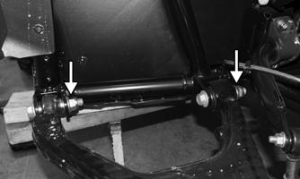
13.When the correct distance is reached, tighten the jam nut to secure the rod end to the trailing arm. Note the orientation of the rod end. It should be parallel to or slightly tipped out to the trailing arm as shown. Do not allow the rod end to be tilted in.
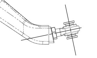
XX222
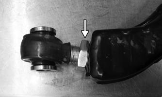
14.Pull back on the rubber cover on the rod end to access the flat area to hold it in the proper position with a wrench.

XX223
15.With the rod end properly tightened, place the shims between the gaps of the rod end and chassis mount.
The placement of the shims will vary since the shims are only meant to fill the gaps on either side of the rod end. They are not for alignment.

XX221
16.Tighten the cap screw to 170 lb-ft (230 N-m). 17.Install the brakes using new “patch-lock” cap screws.
Tighten the cap screws to 35 lb-ft (48 N-m).
X199
18.Secure the brake lines to the trailing arm with the clips and cap screws.Tighten the to 8 ft.-lb (11 N-m). 19.Attach the sway bar link. Tighten to 35 lb-ft (48 N-m). 20.Install the wheels and using a crisscross pattern, tighten the wheel nuts in 20 ft-lb (27 N-m) increments to a final torque of 95 ft-lb (129 N-m). 21.With the vehicle still lifted off the ground, grasp the driver side rear axle and check for movement between the cups. There should be approx. 1/4 in. (6.4 mm) of movement of the axle shaft at full suspension drop.
XX224
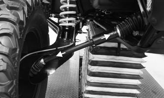
22.If there is not 1/4 in. (6.4 mm) of movement, check the swing arm alignment. Adjust the swing arm until 1/4 in. (6.4 mm) of movement is reached. 23.Lower the vehicle.
Front Sway Bar
REMOVING NOTE: The vehicle does not need to be lifted off the
ground to service the sway bar. However, it does need to be on level ground so no tension is on the sway bar.
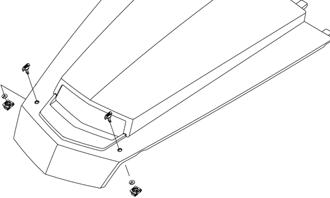
1.Remove the three cable ties and remove the deflector on both sides. The left and right side deflectors are different.

XX248
2.Remove and discard the cap screws and “patch-lock” nuts securing the sway bar to the sway bar link on both sides.

XX249
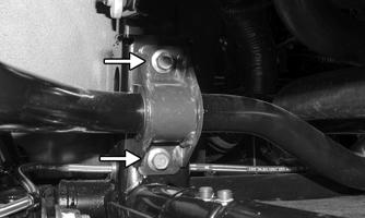
3.Remove the cap screws securing the sway bar to the frame. Account for the bushing retainers and bushings on both sides.
XX252
5.Remove the sway bar through the lower A-arm.
XX253
INSPECTING
1.Inspect the sway bar for any signs of twisting or cracking. 2.Inspect the bushing retainers and bushings for any signs of wear or damage. INSTALLING
1.Install the sway bar into the frame. 2.Install the bushings and bushing retainers on both sides. Using new “patch-lock” cap screws, tighten to 42 ft-lb (57 N-m). 3.Using a new cap screw and nut, secure the sway bar to the sway bar link on both sides. Tighten to 35 ft-lb (48 N-m). 4.Install both deflectors. The textured side goes to the front of the vehicle. Secure to the frame with zip ties.
Rear Sway Bar
REMOVING NOTE: The vehicle does not need to be lifted off the
ground to service the sway bar. However, it does need to be on level ground so no tension is on the sway bar.
1.Remove and discard the cap screws and “patch-lock” nuts securing the sway bar to the sway bar link on both sides.
XX254
2.Remove the cap screws securing the sway bar to the frame. Account for the bushing retainers and bushings on both sides.
XX255
3.Remove the sway bar from the chassis.
XX256
INSPECTING
1.Inspect the sway bar for any signs of twisting or cracking. 2.Inspect the bushing retainers and bushings for any signs of wear or damage. INSTALLING
1.Install the sway bar into the frame.
2.Install the bushings and bushing retainers on both sides.
Use new “patch-lock” cap screws and tighten to 35 ft-lb (48 N-m). 3.Using a new cap screw and nut, secure the sway bar to the sway bar link on both sides. Tighten to 35 ft-lb (48
N-m).
Wheels and Tires
TIRE SIZE
! WARNING
Use only approved tires when replacing tires. Failure to do so could result in unstable vehicle operation.
The vehicle is equipped with low-pressure tubeless tires of the size and type listed in General Information. Do not under any circumstances substitute tires of a different type or size.
! WARNING
Always use the size and type of tires specified. Always maintain proper tire inflation pressure.
CAUTION
Do not mix tire tread patterns. Use the same pattern type on front and rear. Failure to heed this warning could cause poor handling qualities of the vehicle and could cause excessive drive train damage not covered by warranty.
TIRE INFLATION PRESSURE Front and rear tire inflation pressure should be as specified in the General Information/Foreword section. REMOVING
1.Secure the vehicle on a support stand to elevate the wheels. 2.Remove the nuts securing the wheels; then remove the wheels. CLEANING AND INSPECTING
1.Clean the wheels and hubs with parts-cleaning solvent. 2.Clean the tires with soap and water. 3.Inspect each wheel for cracks, dents, or bends. 4.Inspect each tire for cuts, wear, missing lugs, and leaks. INSTALLING Install the wheel; then using a crisscross pattern, tighten the wheel nuts to 95 ft-lb (129 N-m). CHECKING/INFLATING
1.Using an air pressure gauge, measure the air pressure in each tire. Adjust the air pressure as necessary to meet the recommended inflation pressure. 2.Inspect the tires for damage, wear, or punctures.
! WARNING
Do not operate the vehicle if tire damage exists.
NOTE: If repair is needed, follow the instructions
found on the tire repair kit or replace the tire.
Troubleshooting
Problem: Suspension too soft Condition Remedy
1. Spring preload incorrect 1.Adjust preload 2. Spring(s) weak 2.Replace spring(s) 3. Shock absorber(s) damaged 3.Replace shock absorber(s)
Problem: Suspension too stiff Condition Remedy
1. Spring preload incorrect 1.Adjust preload 2. A-arm-related bushings worn 2.Replace bushings
Problem: Suspension noisy Condition Remedy
1. Cap screws (suspension system) loose 1.Tighten cap screws 2. A-arm-related bushings worn 2.Replace bushings
Problem: Vehicle pulling or steering erratic Condition Remedy
1. Vehicle steering is erratic on dry, level surface 1.Check front wheel alignment and adjust if necessary (see Steering/Body/Controls) 2. Vehicle pulls left or right on dry, level surface 2.Check air pressure in tires and adjust to specifications