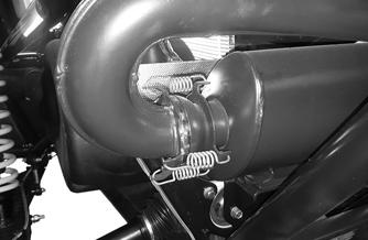
Suspension The following suspension system components should be inspected periodically to ensure proper operation: A. Shock absorber rods bent, pitted, or damaged. B. Reservoirs damp or leaking. C. Shock absorber body damaged, punctured, or leaking. D. Shock absorber eyelets broken, bent, or cracked. E. Shock absorber eyelet bushings worn, deteriorated, cracked, or missing. F. Shock absorber spring broken or sagging. G. Sway bar mountings tight and bushings secure. H. Proper preload and damping for conditions.
Shock Absorbers
XX258
2. If measurement is not as specified, use a jack positioned under the front of the frame to lift and fully extend the front shocks. With a spanner wrench, loosen the preload lock adjustment ring located above the preload adjustment ring; then use an appropriate spanner wrench to rotate the preload adjustment ring in the desired directions shown. Adjust the left- and right-side springs equally as required. Tightening the springs will increase ground clearance, loosening the springs will decrease ground clearance. Secure the preload lock adjustment ring when correct ride height is achieved.
CHECKING/ADJUSTING RIDE HEIGHT
! WARNING Always ensure the vehicle is adjusted to the specified ride height. Failure to do so can result in adverse changes to the vehicle’s ride and handling, which could cause accidents or overturns.
NOTE: The preload collars MUST maintain contact with the spring at all times. Do not remove so much preload that the collar loses contact with the spring and allows the spring to “float” between the upper and lower spring collars. NOTE: Ensure the vehicle is on level ground, the tires are properly inflated to 14 psi (96.5 kPa) for the front tires and 22 psi (151.7 kPa) for the rear tires. This is for an average operating load in the vehicle.
XX130
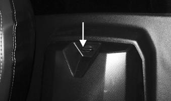
NOTE: Before attempting to adjust the suspension, clean dirt and debris from the sleeve and remove load from the suspension by using a jack to lift the frame and allow the shock to fully extend. Loosen each preload lock adjustment ring; then use an appropriate spanner wrench to adjust the preload adjustment ring to the desired position.
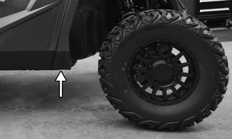
1. Measure from the ground to the bottom of the frame tube in the locations shown behind the front lower A-arms. Measurement should be 14 in. (35.6 cm).
XX130A
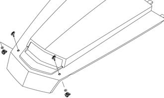
3. On the rear, measure the ground to the bottom of the skid plate. Measurement should be 14 in. (35.6 cm).
143