Drive System GENERAL INFORMATION
Gear cases are 3.6:1. NOTE: Never reuse a lock nut. Once a lock nut has been removed, it must be replaced with a new lock nut. SPECIAL TOOLS
A number of special tools must be available to the technician when performing service procedures in this section. Refer to the current Special Tools Catalog for the appropriate tool description.
PK305
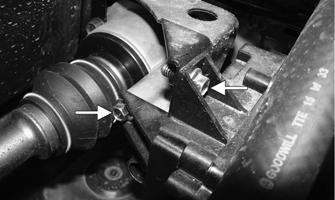
3. From the rear, remove the two cap screws securing the actuator to the differential and bracket.
NOTE: When indicated for use, each special tool
will be identified by its specific name, as shown in the chart below, and capitalized. Description Backlash Measuring Tool (24-Spline Axle) CV Boot Clamp Tool Internal Hex Socket Pinion Gear/Shaft Removal Tool Gear Case Seal Installer Tool Hub Retaining Wrench
p/n 0544-010 Common Tool Common Tool Common Tool 0444-273 0444-270
NOTE: Special tools are available from the Service Department.
Front Drive Actuator
PK306A
4. Remove the rubber access plug found toward the back side of the actuator; then remove the selector shaft circlip and spacer. Discard the circlip.
NOTE: The actuator is not a serviceable component. If it is defective, it must be replaced. NOTE: The actuator will operate only when the ignition switch is in the ON position.
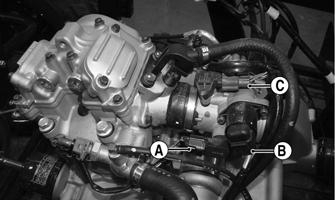
The front drive actuator is located on the right side of the front differential input housing. With the engine stopped and the ignition switch in the ON position, a momentary “whirring” sound can be heard each time the drive select switch is shifted. If no sound is heard, see Electrical System. If the actuator runs constantly or makes squealing or grinding sounds, the actuator must be replaced.
PK034A
REMOVING
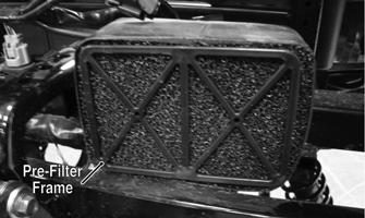
1. Turn the ignition switch to the ON position; then select 2WD LOCK on the drive select switch. Remove the drain plug from the bottom of the differential and allow the fluid to drain; then remove the seat and center floorboard kick panel. 2. Remove the air box and intake tube found below the center floorboard kick panel.
PK035
118