13 minute read
Fuel/Lubrication/Cooling

TROUBLESHOOTING 1.Verify that the electric fuel pump is operating by listening for a “whirring” sound for several seconds after the ignition switch is turned to the ON position.
If no sound can be heard, see EFI Sensors/Components in Electrical System. 2.Check for a flashing EFI icon on the LCD. If EFI is flashing, see EFI Diagnostic System in Electrical
System. 3.Make sure there is sufficient, clean gas in the gas tank. SPECIAL TOOLS A number of special tools must be available to the technician when performing service procedures in this section. Refer to the current Special Tools Catalog for the appropriate tool description. NOTE: When indicated for use, each special tool
will be identified by its specific name, as shown in the chart below, and capitalized.
Description p/n
Oil Pressure Test Kit 0644-495 Tachometer Common Tool
NOTE: Special tools are available from the Service
Department.
Throttle Body
! WARNING
Whenever the fuel hoses are removed (other than for pressure testing), the battery must be disconnected to prevent inadvertent activation of the electronic fuel pump.
! WARNING
Whenever any maintenance or inspection is performed on the fuel system during which there may be fuel leakage, there should be no welding, smoking, open flames, etc., in the area.
REMOVING 1.Turn the ignition switch to the OFF position; then remove the ignition switch key.
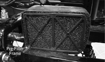
2.Remove the seat and air box assembly. 3.Disconnect the TPS (A), ISC (B), and TMAP (C) connectors from the throttle body assembly.
! WARNING
Do not turn the ignition switch to the ON position with the hoses removed. Gasoline will be pumped by the electric fuel pump causing a safety hazard.
PK170B
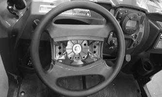
4.Remove the screws from the throttle arm cover and remove the cover. Note the different-length screws.
PK183A
! WARNING
Gasoline may be under pressure. Place an absorbant towel under the connector to absorb any gasoline spray when disconnecting.
5.Loosen the clamp securing the throttle body to the intake manifold boot and remove the throttle body assembly. Note the notch in the intake manifold boot for alignment purposes.

PK184A
6.Use tape to cover and seal the intake opening.
INSTALLING 1.Install the throttle body into the intake manifold boot and secure with the clamp. Tighten to 30 in.-lb.
CAUTION
Any objects or liquid entering the intake opening will fall into the engine causing severe damage if the engine is turned over or started.
2.Connect the throttle cable to the throttle body; then install the throttle arm cover and secure it to the throttle body with the two screws. 3.Connect the electrical connectors to the throttle body components. 4.Install the air filter assembly and secure with the existing hardware. 5.Install the seat.
NOTE: If the throttle body, ECM, TPS, or ISC are
replaced, the EFI system must be synchronized. Use the following procedure.
1.With the key off, depress accelerator pedal to Wide
Open Throttle (WOT). 2.Place the ignition key in the ON position and wait for 10 seconds. 3.Release the accelerator pedal and wait an additional 10 seconds. 4.Turn the key to the OFF position and allow the gauge to shut off.
Gas Tank
! WARNING
Whenever any maintenance or inspection is made on the fuel system during which there may be fuel leakage, there should be no welding, smoking, open flames, etc., in the area.
REMOVING 1.Remove the seat, and engine compartment panel.

PK186
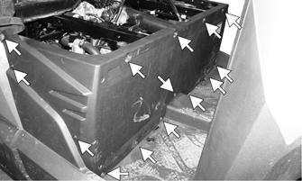
2.Remove the cap screw securing the passenger net restraint to the right side panel assembly; then remove the reinstallable rivet securing the right-rear splash panel to the right side panel assembly.
Remove the remaining reinstallable rivets securing the right-rear splash panel; then remove the splash panel.


PK187A

PK188A
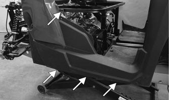
3.Remove the gas cap from the fuel tank; then remove the cap screw and three reinstallable rivets securing the bottom of the right-side panel assembly to the skid plate.
PK189A
4.Carefully pull the right side panel assembly away from the fuel tank filler neck. Use a bungee cord to support the panel. Pull the vent line out of the frame.
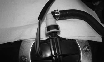
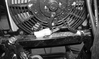
5.Place a shop towel under the fuel line connector; then squeeze the release tab to remove. Disconnect the fuel pump harness connector.
PK191
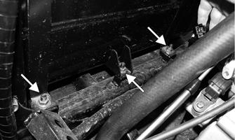
6.Remove the nuts securing the fuel tank straps to the frame and tank mount to frame. Remove the fuel tank from the rear.
PK191
2.Connect the fuel line to the fuel pump; then verify the connector is fully seated to the fuel pump juncture. Connect the fuel pump harness connector to the main wiring harness.
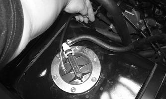
PK192A
CLEANING AND INSPECTING 1.Clean all gas tank components with parts-cleaning solvent. 2.Inspect all hoses for cracks or leaks. 3.Inspect gas tank cap and tank for leaks, holes, and damaged threads. 4.Inspect the fuel level sensor for proper operation (see
EFI Sensors/Components in Electrical System). INSTALLING
1.Place the gas tank into position in the vehicle; then secure the middle tank mount to the frame and two hold-down straps with nuts. Tighten securely.
! WARNING
Whenever any maintenance or inspection is made on the fuel system during which there may be fuel leakage, there should be no welding, smoking, open flames, etc., in the area.
PK193
3.Position the right-side panel assembly so the fuel tank filler neck protrudes through; then secure the side panel assembly to the frame using the three reinstallable rivets and one cap screw.
PK189A
4.Install and secure the right-rear splash panel with reinstallable rivets.
PK188A
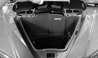
5.Secure the passenger side under seat storage tray using four cap screws and tighten securely.
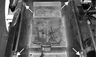
PK194A
6.Install the engine compartment panel; then secure it using the cap screws and reinstallable rivets.
PK151A
7.Install the seat.
Oil Pump
NOTE: Whenever internal engine components wear
excessively or break and whenever oil is contaminated, the oil pump should be replaced.
TESTING OIL PUMP PRESSURE NOTE: The engine must be warmed up to operating
temperature (cooling fan cycling) for this test.
1.Remove the right-rear splash panel. Connect the
Tachometer to the engine or utilize the LCD.

KC370A
NOTE: Some oil seepage may occur when installing
the oil pressure gauge. Wipe up oil residue with a cloth.
3.Block the wheels, place the transmission in neutral, and start the engine. Allow the engine to warm up to operating temperature (with cooling fan cycling). 4.With the engine running at 3000 RPM, the pressure gauge must show 1.12-1.47 kg/cm2 (16-21 psi). 5.Remove the test kit and tachometer from the vehicle and install the oil pressure port plug. Tighten securely. 6.Install the right-rear splash panel. NOTE: If the oil pressure is lower than specified,
check for an oil leak, damaged oil seal, or defective oil pump.
NOTE: If the oil pressure is higher than specified,
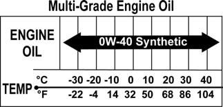
check for too heavy engine oil weight (see General Information/Foreword, Gasoline — Oil — Lubricant), clogged oil passage, clogged oil filter, or improper installation of the oil filter.
REMOVING/DISASSEMBLING Remove the oil pump from the engine (see Left-Side Components in the Engine/Transmission section). INSPECTING 1.Inspect the pump for damage. 2.It is inadvisable to remove the screw securing the pump halves together. If the oil pump is damaged, it must be replaced. NOTE: The oil pump is a non-serviceable compo-
nent and must be replaced as a complete assembly.
ASSEMBLING/INSTALLING Install the oil pump (see Installing Left-Side Components in the Engine/Transmission section).
Liquid Cooling System
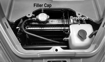
When filling the cooling system, use premixed antifreeze. Verify the coolant level in the reservoir tank is between the FULL and LOW indicator lines. Fill as needed. While the main cooling system is being filled, air pockets may develop. Fill the cooling system to the bottom of the stand pipe in the radiator neck. Run the engine for 3 minutes to allow air to bleed from the cooling system. After the initial fill, shut the engine off, and then “top-off” the cooling system to the bottom of the stand pipe in the radiator neck. Install the radiator cap. NOTE: Use a good quality, biodegradable glycol-
based, automotive-type antifreeze. When filling the cooling system, use a 60/40 coolant/water mixture or one which will satisfy the coldest anticipated weather conditions of the area in accordance with the coolant manufacturer’s recommendations.
! WARNING
Never check the coolant level when the engine is hot or the cooling system is under pressure.
CAUTION
After operating the vehicle for the initial 5-10 minutes, stop the engine, allow the engine to cool down, and check the coolant level. Add coolant as necessary.
COOLING SYSTEM PRESSURE TESTING 1.Remove the front hood and radiator access panel.
Use a readily available pressure tester. Wet the pressure tester seal; then connect the pressure tester to the radiator filler neck. 2.Pump the tester up to 12.8 psi (0.9 kg/cm2). The coolant system should hold this pressure for up to 6 seconds. If it does not, inspect the entire coolant system for leaks. Do not exceed 14.9 psi (1.05 kg/cm2) when pressure testing the coolant system. 3.To test the radiator cap relief pressure, wet the seal on the cap. Connect the tester to the radiator cap. The relief pressure specification for the cap is 12.8 psi (0.9 kg/cm2). If the cap does not relieve pressure as specified, replace the cap. RADIATOR Removing 1.With the vehicle on a flat level surface, set the transmission into the Park position then chock the wheels.
Remove the center and right-side skid plates.
Remove the front hood and radiator access panel.
PK084
PK074A
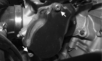
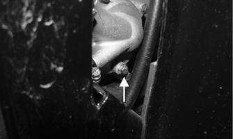
2.Remove the radiator cap; then drain the coolant into a suitable container by removing the drain plug found on the water pump. Account for the washer.
Disconnect the cooling fan wire connector from the main harness.
PK196A
PK197
3.Remove the lower fascia (see Front Fascia/Front
Bumper section).
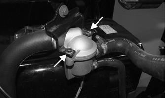
4.Loosen the clamps; then remove the upper and lower main coolant hoses from the radiator. Remove the reservoir hose (B) from the right side of the filler neck and the bleed hose (A) from the back of the filler neck.
PK198A
PK199
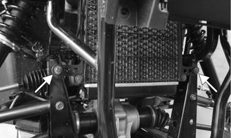
5.Remove the two cap screws securing the upper section of the radiator bracket to the frame; then remove the lower cap screws securing the bracket to the frame.

PK200 PK201A
6.Lower the radiator through the front bumper.
Account for two upper and two lower rubber mounting grommets. NOTE: Removal of the radiator fan does not
require removal of the radiator (see COOLING FAN).
Cleaning and Inspecting 1.Flush internal coolant passage ways of the radiator with distilled water to remove any contaminants.
Flush the external air passage ways with tap water to clear any debris from the cooling fins. Do not use a pressure washer to clear debris from the cooling fins. 2.Inspect the radiator for leaks and damage. 3.Inspect all hoses for cracks and deterioration. 4.Inspect all fasteners and grommets for damage or wear. Installing 1.Place the radiator into position making sure the grommets are correctly installed; then secure to the mounts with the four cap screws and nuts. Tighten to 8 ft-lb. Install the lower fascia.
PK200
PK201A
2.Connect the upper and lower coolant hoses to the radiator and secure with the appropriate hose clamps; then connect the cooling fan wire connector to the main harness. Connect the reservoir hose (B) to the right side of the filler neck and the bleed hose (A) to the back side of the radiator filler neck.
PK198A
PK197
3.Pour the recommended coolant into the radiator and reservoir tank. Bleed the cooling system (see Liquid
Cooling System). 4.Start the engine and warm up to operating temperature. Allow the engine to completely cool to room temperature; then verify the coolant level is at the bottom of the stand pipe in the radiator neck. Check coolant level in reservoir tank. Add coolant as necessary. 5.Install both skid plates, radiator access panel, and front hood.
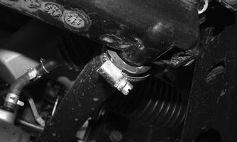
THERMOSTAT Removing 1.Drain approximately one quart of coolant from the cooling system. 2.Remove the two cap screws securing the thermostat housing to the bracket. Account for a thermostat with seal and O-ring installed in the thermostat housing cover.
PK202A.
Inspecting 1.Inspect the thermostat for corrosion, wear, or spring damage. 2.Using the following procedure, inspect the thermostat for proper operation:
A.Suspend the thermostat in a container filled with water. Do not allow the thermostat to contact the container.
B.Heat the water and monitor the temperature with a thermometer.
C.The thermostat should start to open at 176-183°F (80-84°C) and be fully open at 203°F (95°C). Minimum valve lift is approximately 8 mm (0.03 in).
D.If the thermostat does not open, it must be replaced. If the thermostat does not close at room temperature, it must be replaced. 3.Inspect all coolant hoses, connections, and clamps for deterioration, cracks, and wear. NOTE: All coolant hoses and clamps should be
replaced every four years or 4000 miles.
Installing 1.Place the thermostat into the housing; then lightly grease the O-ring in the housing cover. Place the cover onto the thermostat housing; then secure the assembly to the bracket. Secure the cap screws.

PK203
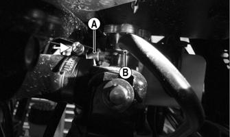
2.Fill the cooling system with the recommended amount of antifreeze. Check for leakage. COOLING FAN Removing 1.Disconnect the fan connector from the main harness. 2.Remove the bleed hose from the routing clamp (A).
Remove the four nuts (B) securing the fan to the radiator bracket; then remove the fan from the radiator.

PK204A
Installing 1.Position the fan assembly on the radiator bracket; then secure with existing hardware. NOTE: Secure the radiator bleed hose using the
routing clamp located toward the top right side of the fan assembly.
2.Secure the fan connector to the main harness. WATER PUMP NOTE: To service the water pump, see Servicing
Right-Side Components.
Troubleshooting
Problem: Starting impaired Condition Remedy
1. Gas contaminated 1.Drain gas tank and fill with clean gas
Problem: Idling or low speed impaired Condition Remedy
1. TPS out of adjustment 1.Adjust TPS
Problem: Medium or high speed impaired Condition Remedy
1. High RPM “cut out” against RPM limiter 1.Decrease RPM speed