9 minute read
Suspension

The following suspension system components should be inspected periodically to ensure proper operation:
A.Shock absorber rods bent, pitted, or damaged.
B.Rubber damper cracked, broken, or missing.
C.Shock absorber body damaged, punctured, or leaking.
D.Shock absorber eyelets broken, bent, or cracked.
E.Shock absorber eyelet bushings worn, deteriorated, cracked, or missing.
F.Shock absorber spring broken or sagging.
G.Sway bar mountings tight and bushings secure. SPECIAL TOOL A special tool must be available to the technician when performing service procedures in this section. A spanner wrench can be found in the tool kit which is located in the glove compartment. This tool is to be used when adjusting spring pre-load.
Shock Absorbers
REMOVING 1.Secure the vehicle on a support stand to elevate the wheels and to fully release the load on the suspension. Remove the wheels.
2.Remove the upper and lower mounting cap screws and lock nuts. Discard the lock nuts. Note the mounting location of the rear upper shock mounts. This mounting location shall not be altered.
! WARNING
Make sure the vehicle is solidly supported on the support stand to avoid injury.
REAR
PK283A
CLEANING AND INSPECTING 1.Clean all shock absorber components in parts-cleaning solvent. 2.Inspect each shock rod for nicks, pits, rust, bends, and oily residue. 3.Inspect all springs, spring retainers, shock rods, sleeves, bushings, shock bodies, and eyelets for cracks, leaks, and bends. INSTALLING 1.Install the shock absorbers with two cap screws and new nuts. Tighten to 32 ft-lb. Install the wheels. 2.Remove the vehicle from the support stand.
Front A-Arms
REMOVING 1.Remove the hubs (see Hub). 2.Remove the brake hose clamps from the knuckle and upper A-arm by removing the cap screws. Support the brake line and caliper using a tie-down.
FRONT Front

PK282A PK316A
PK317
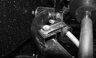
3.Remove the cotter pin and castle nut securing the tie rod end to the knuckle; then remove the tie rod end from the knuckle. Account for the washer. 4.Remove the cap screws securing the ball joints to the knuckle.
CAUTION
Support the knuckle when removing the cap screws or damage to the threads will occur.

PK234A
5.Tap the ball joints out of the knuckle; then remove the knuckle. 6.Remove the lower shock absorber eyelet from the upper A-arm.

PK318
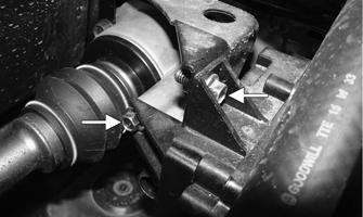
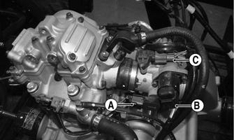
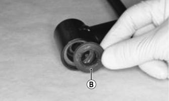
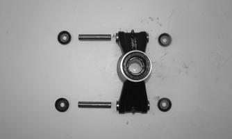
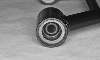
7.Remove the cap screws securing the A-arms to the frame. Account for the A-arm collars (A) and inspect the dust seals (B). By removing both seals, the bearings (C) can be pressed out for replacement.
PK319

PK287A
PK290A

PK291A
8.Remove the snap ring from the ball joint; then remove the ball joint from the A-arm.

PK320
CLEANING AND INSPECTING 1.Clean all A-arm components in parts-cleaning solvent. 2.Clean the ball joint mounting hole of all residual
Loctite, grease, oil, or dirt for installing purposes. 3.Inspect the A-arm for bends, cracks, and worn bushings. 4.Inspect the ball joint mounting holes for cracks or damage. 5.Inspect the frame mounts for signs of damage, wear, or weldment damage. INSTALLING 1.Apply Loctite Primer “T” to the A-arm socket; then apply green Loctite #609 to the entire outside diameter of the ball joint. Install the ball joint into the Aarm and secure with the snap ring.
PK320
2.Install the A-arm assemblies into the frame mounts and secure with the cap screws. Only finger-tighten at this time.
PK319
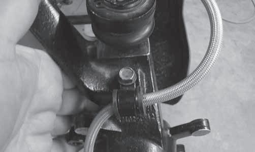
3.Route the brake hose along the upper A-arm. Secure with hose and clamps.
PK317

PK316
4.Secure the lower eyelet of the shock absorber to the lower A-arm. Tighten nut to 32.5 ft-lb. 5.Secure the A-arm assemblies to the frame mounts (from step 2). Tighten the cap screws to 34 ft-lb. 6.Install the knuckle assembly onto the ball joints and secure with cap screws. Tighten to 34 ft-lb.
PK234A
7.Install the tie rod end and secure with the washer and nut (coated with red Loctite #271). Tighten to 25 ftlb; then install a new cotter pin and spread the pin to secure the nut.
NOTE: During assembly, new cotter pins should be
installed.

PK121
8.Apply grease to the hub and drive axle splines; then install the hub (see Drive System).

PK127
9.Secure the brake caliper holder to the knuckle with two new “patch-lock” cap screws. Tighten to 19 ftlb.

PK106B
10. Install the wheels and using a crisscross pattern, tighten the wheel nuts in 20 ft-lb increments to a final torque of 45 ft-lb (steel wheel), 60 ft-lb (aluminum wheel w/black nuts), or 80 ft-lb (aluminum wheel w/ chrome nuts). 11.Remove the vehicle from the support stand.
Rear A-Arms
REMOVING 1.With the vehicle in park, secure the vehicle on a support stand to elevate the wheels.
2.Remove the wheel. Remove the cotter pin; then remove the hub nut to remove the hub. 3.Remove the cap screws and lock nuts securing the knuckles to the A-arms. Discard the lock nuts.
Account for the dust seals and pivot bushings.
! WARNING
Make sure the vehicle is solidly supported on the support stand to avoid injury.
PK284
PK285
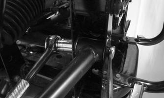
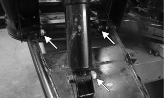
4.Remove the cap screws and lock nuts securing the shock absorber to the frame and lower A-arm; then remove the A-arm. Account for the collars. Discard the lock nuts.
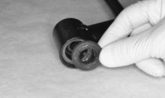
NOTE: To replace either upper or lower A-arm
bearings, remove the collars and dust seals. Press the bearings out using a suitable sized bearing driver.
PK290
PK291 PK287
5.Remove the cap screws securing the rear fascia to the frame. Remove the cap screws and lock nuts securing the upper A-arm to the frame. Account for the collars. Discard the lock nuts.


PK288A

PK289A
CLEANING AND INSPECTING 1.Clean all A-arm components in parts-cleaning solvent. 2.Inspect the A-arm for bends, cracks, and worn bushings or bearings. 3.Inspect the frame mounts for signs of damage, wear, or weldment damage. INSTALLING 1.Press new bearings into the A-arms, using a driver the same size as the outer race of the bearing; then grease and install new seals. 2.Install the A-arm assemblies into the frame mounts and secure with the cap screws and new lock nuts.
Finger-tighten only at this time.
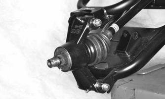
3.Slide the knuckle onto the drive axle and into position on the A-arms; then secure the knuckle with dust seals and pivot bushing to the A-arms with cap screws and new lock nuts. Tighten to 35 ft-lb. 4.Tighten the hardware securing the A-arms to the frame mounts (from step 1) to 35 ft-lb. 5.Secure the shock absorber to the frame with a cap screw and new lock nut. Tighten to 35 ft-lb. 6.Secure the shock absorber to the lower A-arm with a cap screw and new lock nut. Tighten to 35 ft-lb. 7.Secure the rear fascia to the frame with the cap screws. Tighten securely. 8.Grease the splines of the hub; then place the hub onto the axle. Install the hub nut and tighten to 200 ft-lb.
Install a new cotter pin. Attach a grease gun to the fitting and lubricate the knuckle pivot bushings. 9.Install the wheels and using a crisscross pattern, tighten the wheel nuts in 20 ft-lb increments to a final torque of 45 ft-lb (steel wheel), 60 ft-lb (aluminum wheel w/black nuts), or 80 ft-lb (aluminum wheel w/chrome nuts). 10.Remove the vehicle from the support stand.
Wheels and Tires
TIRE SIZE
! WARNING
Use only approved tires when replacing tires. Failure to do so could result in unstable vehicle operation.
This vehicle is equipped with low-pressure tubeless tires of the size and type listed in the General Information section. Do not under any circumstances substitute tires of a different type or size.
TIRE INFLATION PRESSURE Front and rear tire inflation pressure should be 82.7 kPa (12 psi). REMOVING 1.Secure the vehicle on a support stand to elevate the wheels.
2.Remove the nuts securing the wheels; then remove the wheels. CLEANING AND INSPECTING 1.Clean the wheels and hubs with parts-cleaning solvent. 2.Clean the tires with soap and water. 3.Inspect each wheel for cracks, dents, or bends. 4.Inspect each tire for cuts, wear, missing lugs, and leaks. INSTALLING 1.Install each wheel on its hub and secure with the existing hardware.
! WARNING
Always use the size and type of tires specified. Always maintain proper tire inflation pressure.
! WARNING
Do not mix tire tread patterns. Use the same pattern type on front and rear. Failure to heed warning could cause poor handling qualities of the vehicle and could cause excessive drivetrain damage not covered by warranty.
! WARNING
Make sure the vehicle is solidly supported on the support stand to avoid injury.
2. Using a crisscross pattern, tighten the wheel nuts in 20 ft-lb increments to a final torque of 45 ft-lb (steel wheel), 60 ft-lb (aluminum wheel w/black nuts), or 80 ft-lb (aluminum wheel w/chrome nuts). CHECKING/INFLATING 1.Using an air pressure gauge, measure the air pressure in each tire. Adjust the air pressure as necessary to meet the recommended inflation pressure. 2.Inspect the tires for damage, wear, or punctures. ! WARNING
Do not operate the vehicle if tire damage exists.
NOTE: If repair is needed, follow the instructions
found on the tire repair kit or remove the wheel and have it repaired professionally.
NOTE: Be sure all tires are the specified size and
have identical tread pattern.
Troubleshooting
Problem: Suspension too soft Condition Remedy
1. Spring preload incorrect 1.Adjust preload 2. Spring(s) weak 2.Replace spring(s) 3. Shock absorber damaged 3.Replace shock absorber 4. Rear shock absorbers too soft 4.Check and adjust air pressure in shocks
Problem: Suspension too stiff Condition Remedy
1. Spring preload incorrect 1.Adjust preload 2. A-arm-related bushings worn 2.Replace bushing
Problem: Suspension noisy Condition Remedy
1. Cap screws (suspension system) loose 1.Tighten cap screws 2. A-arm-related bushings worn 2.Replace bushings
Problem: Vehicle pulling or steering erratic Condition Remedy
1. Vehicle steering is erratic on dry, level surface 1.Check front wheel alignment and adjust if necessary (see Steering/Body/Controls — Front Wheel Alignment) 2. Vehicle pulls left or right on dry, level surface 2.Check air pressure in tires and adjust to specifications