28 minute read
Steering/Body/Controls

The following steering components should be inspected periodically to ensure safe and proper operation:
A.Steering wheel secure.
B.Steering has equal and complete full-left and full-right turning capability.
C.Steering sector mounting bolts tight.
D.Ball joints not worn, cracked, or damaged.
E.Tie rods not bent or cracked.
F.Knuckles not worn, cracked, or damaged.
G.Cotter pins not damaged or missing.
H.Steering wheel tilt locks securely. The frame and welds should be checked periodically for damage, bends, cracks, deterioration, broken components, and missing components.
Steering Wheel
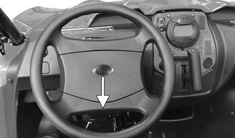
REMOVING 1.Remove the steering wheel cover by squeezing the retaining tabs together (located behind the steering wheel); then match mark the steering shaft and steering wheel. NOTE: Any time steering components are disassem-
bled, all connecting components should be marked for proper alignment during assembling.
2.Remove the nut securing the steering wheel and remove the steering wheel. INSPECTING 1.Inspect the steering wheel for cracks, missing padding, or broken spokes. 2.Inspect the splines for wear. 3.Check that the steering wheel is not bent. INSTALLING 1.Install the steering wheel aligning the two match marks. Place the washer onto the steering shaft; then apply a drop of red Loctite #271 to the threads of the nut and secure the steering wheel. Tighten to 25 ft-lb. NOTE: If a new steering wheel is being installed,
mark the wheel as close as possible to the old wheel mark; then check for proper positioning with the front wheels straight forward.
PK112
2.Install the steering wheel cover.
Steering System
REMOVING STEERING SHAFT ASSEMBLY 1.Remove the steering wheel cover and steering wheel.
Account for the washer. Note the match marks for assembly purposes.
PK070A.
2.Remove the reinstallable plastic rivets and cap screws securing the plastic steering column covers; then remove both upper and lower covers. Account for the rubber plugs.
PK113A
PK114A
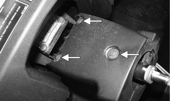
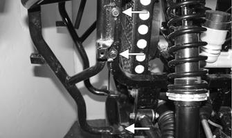
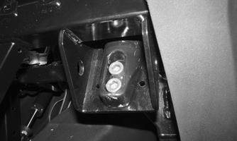
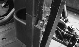
3.Remove the steering shaft lift support cap screw and nut. Account for the two spacers.
PK115
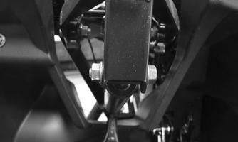
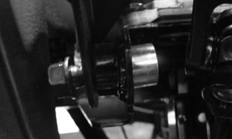
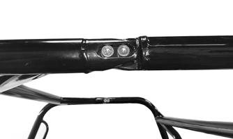
4.Remove the two nuts securing the cap screws at the steering shaft housing pivot point.
PK116A
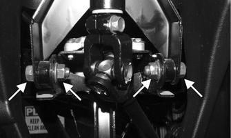
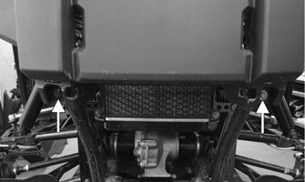
5.Remove the two cap screws with washers (located toward the left of the steering shaft housing) securing the dashboard to the frame. Remove the left side steering shaft housing cap screw first; then remove the right. Remove the collars from the inside.
PK117A
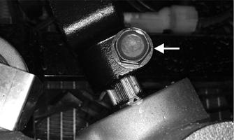
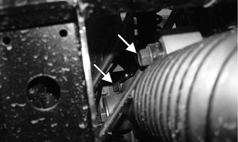
6. Note the matching alignment marks on the pinion shaft and rack/pinion housing for assembly purposes.
PK118A
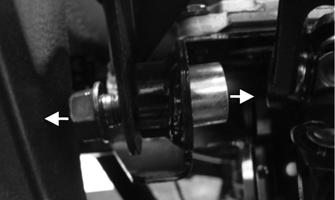
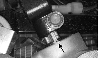
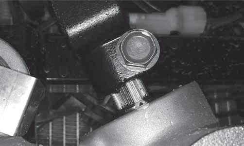
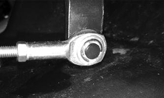
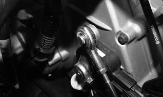
7.Remove the cap screw securing the lower steering shaft joint to the pinion shaft; then slide the joint free of the pinion.
PK118B
8.Align the original marks on the upper steering shaft to the steering column housing.
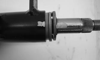
9.With the marks still aligned from step 8, on the opposite side of the column, match mark the upper intermediate shaft joint to the bottom of the steering column housing. Remove the cap screw securing the joint to the upper steering shaft; then remove the intermediate steering shaft. Account for the two standard washers and one wave washer.
PK119
INSTALLING STEERING SHAFT ASSEMBLY 1.Align the marks on the upper steering shaft to the steering column housing.
PK120
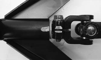
2.Align the gap in the upper intermediate shaft joint to the previously marked location on the steering column housing. Secure with the cap screw; then tighten to 15 ft-lb.
PK119
3.Align the match marks on the splined pinion shaft to the marks on the rack/pinion housing.
PK118A
4.With the marks still aligned from the upper steering shaft to the steering column housing, place the lower intermediate shaft joint onto the splined pinion shaft of the rack/pinion assembly. Tighten the cap screw to 15 ft-lb.
PK118B
5.Place the cap screws into position; then install each spacer into the frame. Install the steering shaft housing. Secure to the frame with two cap screws and nuts. Tighten to 23 ft-lb.
PK117
6.With the spacers in place, secure the lift support to the steering column using the cap screw and nut.
Tighten securely.
PK115
7.Install both upper and lower steering column covers and secure using the cap screws and reinstallable inserts. Insert the rubber plugs into the covers. 8.Install the steering wheel (see Steering Wheel in this section). REMOVING RACK AND PINION 1.Remove the steering shaft; then remove the front wheels. 2.Remove the cotter pins and castle nuts securing the tie rod ends to the knuckle. Account for the washers; then remove the tie rod ends from the knuckles.

PK121
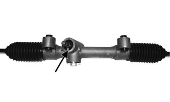
3.Remove the cap screws securing the steering rack assembly to the frame and remove from the left side.
PK122A
INSPECTING RACK AND PINION 1.Inspect the tie rod ends for damaged threads, torn boots, or excessive wear. 2.Inspect the tie rods for bends or deformation. 3.Inspect the rack and pinion-to-tie rod boots for tears or deterioration.
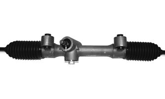
PR785
4.Verify the cable ties for each boot are secure and in good condition. Replace if necessary. 5.Check that the steering assembly operates smoothly with no binding from full-left to full-right position. 6.Inspect for grease seepage from the steering assembly. NOTE: The steering assembly (rack and pinion) is
not repairable and must be replaced as an assembly; however, the tie rods and boots are replaceable.
INSTALLING RACK AND PINION 1.From the left side, install the steering assembly (rack and pinion) to the frame assembly and secure with two cap screws. Tighten to 34 ft-lb. 2.Place the tie rod ends into the knuckles. Install the washers; then secure with the castle nuts (coated with red Loctite #271). Tighten to 25 ft-lb; then install new cotter pins. NOTE: If the slots in the castle nut are not aligned
with the hole in the tie rod end, tighten until the cotter pin can be installed.
3.Install the steering shaft (see INSTALLING STEER-
ING SHAFT ASSEMBLY). 4. Install the wheels and using a crisscross pattern, tighten the wheel nuts in 20 ft-lb increments to a final torque of 45 ft-lb (steel wheel), 60 ft-lb (aluminum wheel w/black nuts), or 80 ft-lb (aluminum wheel w/ chrome nuts). REMOVING TIE RODS 1.Remove the steering rack assembly (see REMOV-
ING RACK AND PINION in this section). 2.Support the steering rack assembly in a suitable holding fixture or bench vise; then cut the securing band and slide the boot toward the outer tie rod end. 3.Using a punch or chisel, bend the lock washer away from the flats on the tie rod joint.
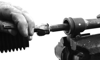
PR780
4.Using an appropriate crowfoot and backing wrench, remove the tie rod assembly. NOTE: Tie rods come as a complete assembly. No
further disassembly is required.
5.Remove and discard the lock washer. INSTALLING 1.Remove the tie rod end and lock nut from the tie rod; then install the tie rod boot onto the tie rod. 2.Install the tie rod lock nut and tie rod end. 3.Coat the tie rod joint threads with red Loctite #271; then with a new lock washer, thread the tie rod into the rack.
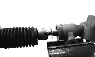
PR784
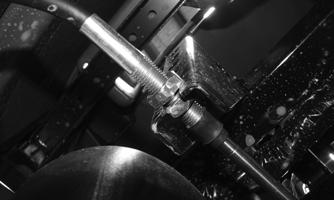
4.While holding the rack shaft with a wrench, tighten the tie rod joint to 37 ft-lb using an appropriate crowfoot wrench.
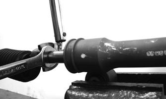
PR781
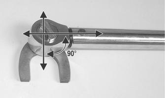
NOTE: Always attach the crow-foot to the torque
wrench with the open end 90° to the torque wrench handle to ensure accurate torque application.
PR528A
5.Install the boot onto the rack and secure with the nylon tie. 6.Center the rack in the steering rack assembly and align the white paint line on the pinion with the mark on the rack housing.
PR785A
Steering Knuckles
REMOVING AND DISASSEMBLING 1.Secure the vehicle on a support stand to elevate the wheel; then remove the wheel.
! WARNING
Make sure the vehicle is solidly supported on the support stand to avoid injury.
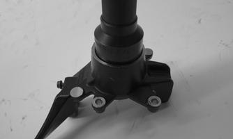
2.Remove the cotter pin and nut securing the hub. 3.Remove the brake caliper. 4.Remove the hub assembly; then remove the brake line from the knuckle. 5.Remove the cotter pin from the tie rod end and remove the tie rod end from the knuckle. Account for the washer. 6.Remove the two cap screws securing the ball joints in the knuckle.
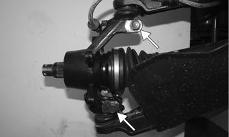
PK123A
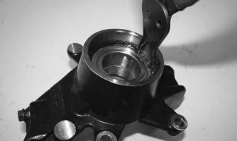
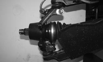
7.Tap the ball joint end out of the knuckle; then remove the knuckle. 8.Using a suitable seal puller, remove both seals from the knuckle. Note the two different seals.
PK124
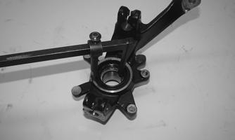
9.Remove the snap ring securing the bearing in the knuckle; then press the bearing out of the knuckle.
PK125
CLEANING AND INSPECTING 1.Clean all knuckle components. 2.Inspect the bearing for pits, scoring, rusting, or premature wear. 3.Inspect the knuckle for cracks, breaks, or galling of the bearing surface. ASSEMBLING AND INSTALLING 1.Using a suitable press and driver, press the bearing into the knuckle until firmly seated; then install the snap ring.
PK126
PK125
2.Grease the bearing and seals; then using a suitable sized seal driver, install both inner and outer seals.
The large lipped seal installs into the inner side of the knuckle. 3.Install the knuckle to the upper and lower ball joints and secure with the two cap screws. Tighten to 35 ftlb.
PK123
4.Install the tie rod end onto the knuckle; then install the washer and secure with the nut (coated with red
Loctite #271). Tighten to 30 ft-lb; then install a new cotter pin and spread the pin. NOTE: During assembling, new cotter pins should
be installed.
5.Apply a small amount of molybdenum grease to the hub splines.

PK127
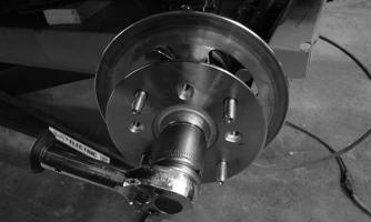
6.Install the hub assembly onto the splines of the shaft.

PK128
7.Using Hub Retaining Wrench, secure the hub assembly with the nut. Tighten to 200 ft-lb.
PK129
8.Install a new cotter pin. NOTE: If necessary, further tighten the hub nut
clockwise to allow the installation of a new cotter pin.
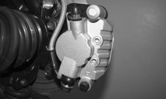
9.Secure the brake line to the knuckle; then secure the brake caliper to the knuckle with the two new
“patch-lock” cap screws. Tighten to 20 ft-lb.

PK106
10. Install the wheels and using a crisscross pattern, tighten the wheel nuts in 20 ft-lb increments to a final torque of 45 ft-lb (steel wheel), 60 ft-lb (aluminum wheel w/black nuts), or 80 ft-lb (aluminum wheel w/ chrome nuts). 11.Remove the vehicle from the support stand.
Accelerator Pedal
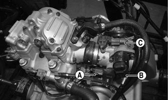
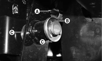
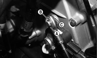
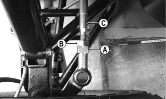
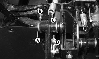
REMOVING Release the return spring (A) from the accelerator pedal, then remove the throttle cable from the pedal. Remove the E-clip (B); then remove the pedal. Account for the washers (C).
PK131A
INSTALLING Place one washer into position. Install the pedal and then the second washer. Secure with a new E-clip. Install the throttle cable and return spring to the pedal.
CAUTION
Check for smooth accelerator cable operation. Verify the pedal returns to the idle position.
REMOVING NOTE: The dash must be removed prior to replace-
ment of the shift lever (see Dashboard).
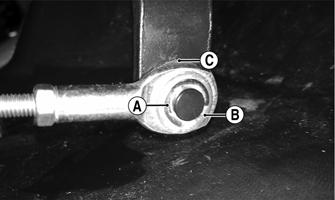
1.Remove the E-clip (A) and washer (B) connecting the shift cable to the shift lever. Account for the bushing (C).
PK132A
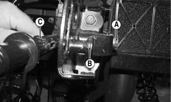
2.Remove the cap screw (A) and washer securing the shift guide (B) to the shift lever shaft. Remove the guide and shift lever (C). Account for the three washers.
PK133A
INSTALLING 1.Place one larger outside diameter washer onto the shift lever shaft then grease; then slide the shift lever shaft into the frame. 2.Place a second larger outside diameter washer onto the shift lever shaft; then install the shift guide onto the shift lever shaft. Secure using a new patch lock cap screw with the smaller outside diameter washer.
PK133
3.With the bushing (C) in place on the shift lever shaft, install the shaft cable. Secure it with a washer (B) and a new E-clip (A).
PK132A
4.Install the dashboard (see Dashboard). 5.Check for proper shifter operation (see Periodic
Maintenance/Tune-Up — Shift Cable).
Shift Cable
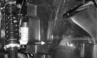
REMOVING 1.Remove the seat; then remove the plastic rivet securing the front left inner fender panel. Remove the panel.
PK134A
2.From under the dash, remove the E-clip securing the shift cable end to the shift lever guide. Account for the washer and bushing.
PK132
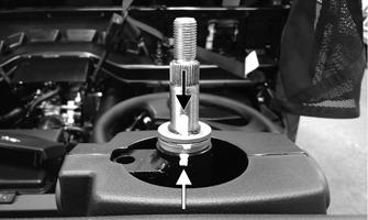
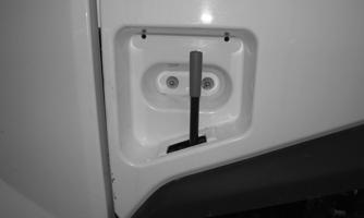
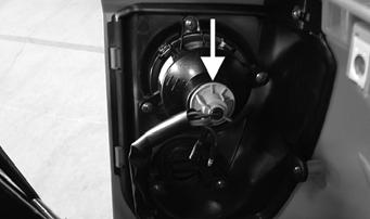
3.From under the front body panel, measure the installed length of the threads; then loosen the cable adjuster nuts. Slide the cable out of the bracket.
PK101
4.From under the seat, remove the E-clip (A) securing the cable end to the shift arm stud. Account for the washer (B) and bushing (C).
PK100A
5.Measure the installed set length of the threads; then loosen the adjuster nuts. Remove the shift cable from the bracket. 6.Remove the center floorboard panel and any cable ties securing the shift cable to the chassis noting their location; then remove the shift cable.
PK102
NOTE: If the cable is being replaced, connect the
new cable to the end of the existing cable and pull the new cable into place.
INSTALLING 1.Route the cable into position making sure there are no kinks or sharp bends. 2.Guide the shift cable into the shift cable bracket.
Install the cable end to the shift arm stud and secure with a new E-clip. Using the measured length (from step 5), install the shift cable into the bracket; then secure the adjuster nuts.
PK100
3.From under the front body panel, guide the shift cable into the bracket; then using the measured length (from step 3), secure the adjuster nuts to the bracket. Install the cable end to the shift lever attachment using a new E-clip. Tighten each nut to secure the cable to the bracket. 4.Fasten the shift cable to the chassis with the previously identified cable tie locations. 5.Shift the transmission through all positions making sure the each gear position illuminates the appropriate gears selected and that Park Indicator illuminates only when fully in Park. Adjust as necessary. 6.Install the center floorboard panel, front right access panel, and seat.
LCD Gauge
REMOVING/INSTALLING To remove the gauge, pull out on one side of it; then disconnect the multi-pin connector and remove the gauge.
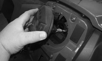
PK135
To install the gauge, connect the multi-pin connector and press the gauge into the dash. NOTE: Ensure the rubber mounting ring is ori-
ented correctly on the tab and seats fully through the dash.
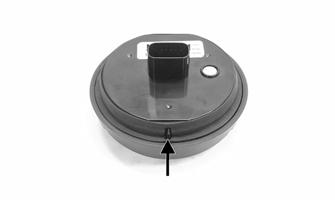
WT601A
Front Wheel Alignment
NOTE: All measurements and adjustments must be
made with the vehicle unloaded.
Mark the centerline of the front tires at the front and rear of the tire; then using a tape measure, measure and record the distance between the marks at the front and rear. The front measurement should be 0-6 mm (0-1/4 in.) greater than the rear measurement (toe-out).
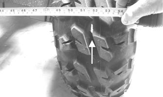
PR087A
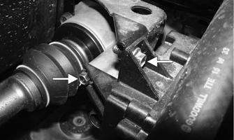
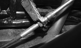
1.Center the steering wheel; then using an open-end wrench to hold the tie rod ends (A), loosen the rightside and left-side jam nuts (B).
TXR002B
PK079A
CAUTION
Always use a wrench to hold the tie rod ends when loosening or tightening the jam nuts or damage to the boots could occur.
2.Turn the left-side and right-side tie rods (C) in equal increments to achieve the proper toe-out; then tighten the jam nuts to 28 ft-lb.
Front Fascia/Front Bumper
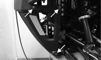
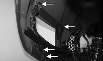
REMOVING 1.Remove the eight cap screws securing the lower front fascia to the frame from both sides of the vehicle; then remove the lower fascia.
PK136A
PK137A
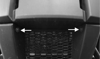
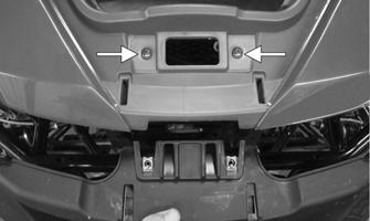
2.Remove the two cap screws at the front of the upper fascia secured to the frame; then remove the cap screws securing the upper fascia from around the headlights.
PK139A
PK138A
3.Remove the two remaining machine screws; then separate the upper fascia from the front body panel for removal.
PK140A
4.Disconnect both headlight assemblies; then remove the cap screws securing the bumper to the frame from both sides of the vehicle. Remove the bumper.
PK141A
5.Remove the two Z-shaped retaining clips securing each side of the headlights to the bumper; then remove the tilt adjust knob. INSTALLING 1.With the headlights installed, place the front bumper into position and secure the cap screws. Tighten to 22 ft-lb. Connect each headlight connector.
PK141A
2.Place the upper fascia into position and secure the cap screws.
PK140A
PK139A
PK138A
3.Secure and install the lower fascia to the frame using the cap screws.
PK137A PK136A
4.Check and adjust headlight aim (see Headlight —
Taillight/ Brake Light — Reverse Light section).
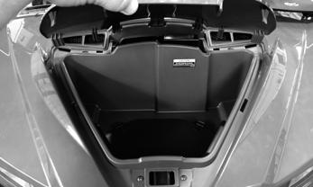
Hood/Front Storage Compartment
To access the front storage compartment, lift up firmly on the front of the hood to remove. To install, align the tabs of the hood into the front panel slots and press down firmly to secure.
PK084
Front Body Panel
REMOVING 1.Remove the front fascia (see Front Fascia/Front
Bumper section); then remove both side panel assemblies (see Dashboard — step 5). 2.With assistance remove the cap screws and nuts securing the front half of the ROPS assembly; then remove. Discard the cap screws and nuts.
PK069
PK089
3.Remove the eight plastic rivets securing the top of the dashboard to the front body panel; then separate the panel from the dash. 4.Remove the front access panel; then remove the
PDM (A) and diagnostic plug (B) from the body panel. Remove the two remaining cap screws securing the body panel to the frame.
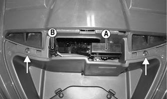
PK144A PK143
INSTALLING 1.Install the front body panel; then secure it to the top of the dashboard using the plastic rivets. Place the
PDM and diagnostic plug into position; then using the two cap screws, secure the panel to the frame.
PK144A
2.Install the front fascia (see Front Fascia/Front Bumper) and both side panel assemblies (see Dashboard — step 5). 3.Using new cap screws and nuts and with assistance, install the front half of the ROPS assembly. Finger tighten all fasteners first; then tighten to 47 ft-lb.
Floor
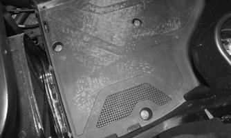
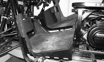
REMOVING 1.Remove the dashboard (see Dashboard). 2.Remove the cap screws and plastic rivets securing the center foot guard. Remove the guard.
PK145A
3.Remove the accelerator pedal (see Accelerator Pedal in this section). 4.Remove the cotter pin and clevis pin securing the master cylinder plunger to the brake pedal lever.
Remove the E-clip (A) securing the brake pedal lever to the bracket. Release the return spring (C). Remove the brake lever and account for the washers (B).
PK147A
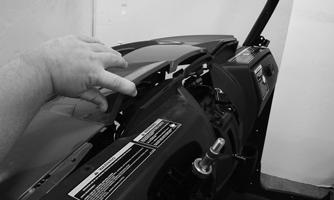
5.Remove the cap screws (A) and plastic rivets (B) to remove both left and right side panel assemblies.
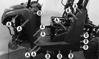
PK093A
NOTE: To remove the right side panel assembly, the gas tank cap and an additional plastic rivet, located behind the right-rear ROPS tube securing the rear splash panel to the side panel, must be removed.
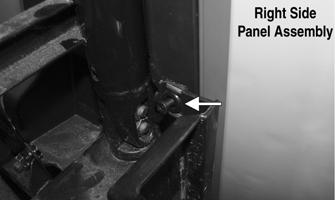
PK148A
PK146
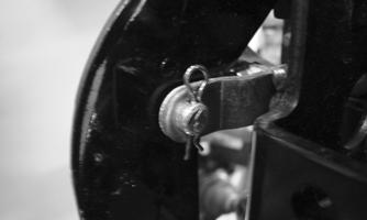
6.Remove the remaining cap screws securing the floor board to the frame from each side of the vehicle.
PK149
7. Remove the floorboard.
PK150
CLEANING AND INSPECTING 1.Clean the floor with soap and water. 2.Inspect the floor for cracks or holes.
INSTALLING 1.Place the front of the floor into position in the vehicle first; then lower the rear and push down into position. 2.Secure the floor with the cap screws. 3.Install the accelerator and brake pedals using new Eclips. Additionally, use a new cotter pin when securing the clevis pin of the master cylinder push rod. 4.Install the center foot guard; then install the dashboard (see Dashboard).
Dashboard
REMOVING 1.Remove the seat, steering wheel, shift lever handle, and steering column covers. 2.Remove the cap screws and plastic rivets securing the engine compartment panel to the frame; then remove the panel.
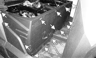
PK151A
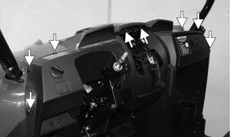
3.Remove and disconnect the instrument gauge; then remove the four Allen-head cap screws securing the center dash panel. Remove the ignition switch from the panel; then disconnect the 2WD/4WD switch, override switch, and accessory plug.
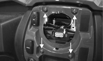
PK152A
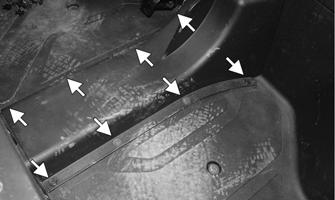
4.Remove the plastic rivets securing the rubber splash guard from behind the accelerator and brake pedals; then remove the guard.
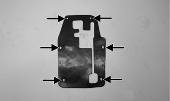
PK153A
5.From under the dash, disconnect the light switch connector; then remove the female side of the connector from the frame.
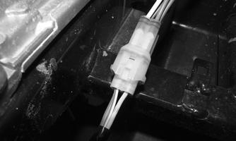
PK154
6.Remove the cap screws (A) and plastic rivets (B) to remove both left and right side panels.
PK093B
NOTE: To remove the right side panel assembly, the
gas tank cap and an additional plastic rivet, located behind the right-rear ROPS tube securing the rear splash panel to the side panel, must be removed.
PK148A
7.Remove the cap screws and plastic rivets securing the dashboard to the front body panel and frame; then separate the top of the dash from the front body panel.
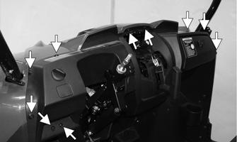
PK142B
PK143
8.Remove the two remaining cap screws securing the bottom of the dash to the floorboard panel. Remove the dashboard.
PK155
INSTALLING 1.To aid in installation of the dashboard, remove the bottom of the lift support from the steering column via the cap screw and nut. Account for the bushing.
Tilt the lift support out; then install the dashboard into position.
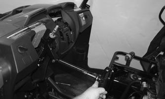
PK156
2.Install the bushing; then secure the bottom of the lift support to the steering column via the cap screw and nut. Tighten securely. 3.Install and secure the two cap screws located toward the outside edges of the dash to secure to the floorboard.
PK155
4.Install the left and right side panel assemblies using cap screws (A) and plastic rivets (B).
PK093B
PK148A
5.Align the top of the dashboard with the front body panel; then using eight plastic rivets and two cap screws, secure the dash to the front body panel and frame.
PK142B
6.Connect the headlight switch connector and install the ignition switch to the center dash panel. Place the center dash panel into position and connect the 2WD/4WD switch, override switch, ignition switch, and 12V accessory outlet. Secure the center dash panel to the dashboard with the four Allen-head cap screws.
PK152
7.Install the gauge, shift lever handle, and steering column covers. 8.Align and install the steering wheel (see Steering
Wheel in this section). Tighten to 25 ft-lb. Install the steering wheel cover.
Belly Panel
REMOVING 1.Remove the body screws securing the belly panel to the underside of the frame. 2.Remove the belly panel. INSTALLING 1.Place the belly panel into position on the underside of the frame. 2.Install the body screws. Tighten securely.
Muffler
REMOVING 1.Remove the two exhaust springs at the muffler/ exhaust pipe juncture.
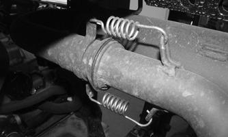
PK168
2.Slide the muffler assembly forward and clear of the holder pins. Account for the gasket. INSPECTING 1.Inspect the muffler externally for cracks, holes, and dents. 2.Inspect the muffler internally by shaking the muffler back and forth and listening for rattles or loose debris inside the muffler.
NOTE: For additional details on cleaning the muffler/
spark arrester, see Periodic Maintenance/Tune-Up.
INSTALLING 1.With the gasket in place, position the muffler onto the holder pins and slide rearward into position. 2.Secure the muffler to the exhaust pipe with the two exhaust springs.
Cargo Box
REMOVING 1.Disconnect both taillight/brake light connectors. Pull the wiring out of the cargo box frame.
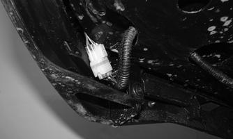
PK157
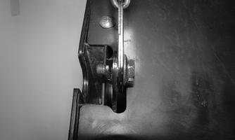
2.Raise the cargo box; then remove the nuts securing the lower lift supports to the frame. Account for the washers. Do not allow the cargo box to tilt rearward.
Tilt the cargo box forward and latch it to the frame.
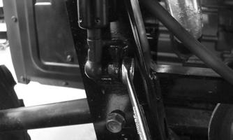
PK158
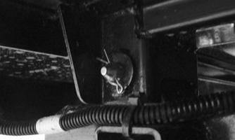
3.Remove the retaining clips from each clevis pin; then remove both pivot pins.
PK159
4.Remove the nuts securing the lift supports to the bottom of the cargo box; then remove the lift supports. 5.With the help of an assistant or an adequate lift, release the cargo box latch; then remove the cargo box from the vehicle.
CLEANING AND INSPECTING 1.Clean all cargo box components with soap and water. 2.Inspect the cargo box for cracks, tears, and loose hardware. 3.Inspect the welds of the cargo box frame for cracking or bending. 4.Inspect the cargo box gate latches for smooth operation. INSTALLING 1.With the help of an assistant or an adequate lift, set the cargo box into position on the frame. Lightly grease the pivot housings; then insert each clevis pin from the inside out. Secure the retaining clips to the end clevis pins. 2.With the cargo box still lowered, connect the lift supports to the bottom of the cargo box. Install each nut and tighten securely. 3.Raise the cargo box. Do not allow it to tilt fully rearward. Align and connect the lift support to the frame; then install the nuts. Tighten securely. 4.Lower the cargo box and lock into position. 5.Route the wiring harness through the bottom corner of the cargo box; then connect the taillight/brake light connectors.
Tailgate
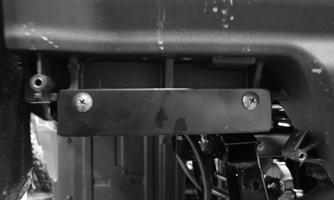
REMOVING 1.Leave the tailgate latched to the cargo bed and remove the cap screws securing the cargo bed cables to the tailgate.
PK323
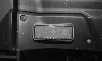
2.Remove both left and right side rear reflector panels by removing the two cap screws securing each to the tailgate assembly.
PK324
3.Remove the two cap screws securing both left and right pivot panels to the tailgate. Unlatch the tailgate from the cargo bed; then with the aid of an assistant, tilt the tailgate down and lift up to remove.
PK325
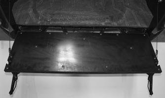
INSTALLING 1.Place the tailgate into position; then tilt up and latch to the cargo bed.
PK326
2.Secure each pivot panel using the two cap screws. Install each rear reflector panel using the two cap screws.
PK325
PK324
3.Using the shoulder head cap screws, secure the cargo bed cables to the tailgate.
Taillight Assembly
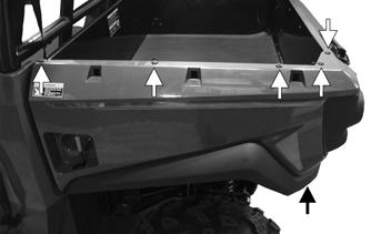
REMOVING 1.Remove the cap screws and lock nuts securing the taillight assembly to the ROPS tube. 2.Remove the two nuts and cap screws securing the steel tie-down to the cargo box.
PK023
3.Remove the six plastic screws securing the rear fender to the cargo box. Remove the rear fender.
PK064A
4.Remove the taillight/brake light socket by rotating the socket counterclockwise. Rotate the bulb counterclockwise to remove from socket.
PK328
INSPECTING 1.Inspect wiring harness, three-prong connector, lens, base, cap screws, and socket for damage. 2.Inspect all wires for corroding, pinching, and cracking. 3.Inspect the bulb for wattage, voltage, and proper operation. INSTALLING 1.Place the rear fender onto the cargo box and secure with the six plastic screws. Secure the tie-down with the two nuts and cap screws. 2.Connect the taillight/brake light connector.
Seat
REMOVING/INSTALLING 1.To remove the seat, raise the front of the seat and slide it forward. 2.To install the seat, slide the rear of the seat into the seat retainers and push down firmly on the front of seat.
Troubleshooting
Problem: Handling too heavy or stiff Condition
Remedy
1. Front wheel alignment incorrect 2. Steering shaft binding 3. Tire inflation pressure incorrect 4. Tie rod ends seizing
Problem: Steering oscillation Condition
1.Adjust alignment 2.Lubricate/replace steering shaft 3.Adjust pressure 4.Replace tie rod ends
Remedy
1. Tires inflated unequally 2. Wheel(s) bent 3. Wheel hub studs loose — missing 4. Wheel hub bearing worn — damaged 5. Tie rod ends worn — loose 6. Tires defective — incorrect 7. A-arm bushings damaged 8. Bolts — nuts (frame) loose 1.Adjust pressure 2.Replace wheel(s) 3.Tighten — replace wheel studs 4.Replace bearing 5.Replace — tighten tie rod ends 6.Replace tires 7.Replace bushings 8.Tighten bolts — nuts
Problem: Steering pulling to one side Condition Remedy
1. Tires inflated unequally 1.Adjust pressure 2. Front wheel alignment incorrect 2.Adjust alignment 3. Wheel hub bearings worn — broken 3.Replace bearings 4. Frame distorted 4.Repair — replace frame 5. Shock absorber defective 5.Replace shock absorber
Problem: Steering impaired Condition Remedy
1. Tire pressure too high 1.Adjust pressure 2. Steering linkage worn 2.Replace linkage 3. Cap screws (suspension system) loose 3.Tighten cap screws
Problem: Tire wear rapid or uneven Condition Remedy
1. Wheel hub bearings worn — loose 1.Replace bearings 2. Front wheel alignment incorrect 2.Adjust alignment
Problem: Steering noise Condition Remedy
1. Caps screws — nuts loose 1.Tighten cap screws — nuts 2. Wheel hub bearings broken — damaged 2.Replace bearings 3. Lubrication inadequate 3.Lubricate appropriate components
Problem: Rear wheel oscillation Condition Remedy
1. Rear wheel hub bearings worn — loose 1.Replace bearings 2. Tires defective — incorrect 2.Replace tires 3. Wheel rim distorted 3.Replace rim 4. Wheel hub cap screws loose 4.Tighten cap screws 5. Rear suspension arm-related bushing worn 5.Replace bushing 6. Rear shock absorber damaged 6.Replace shock absorber 7. Rear suspension arm nut loose 7.Tighten nut