12 minute read
General Information/Foreword

This Service Manual contains service, maintenance, and troubleshooting information for the 2020 Prowler 500. The complete manual is designed to aid service personnel in service-oriented applications. This manual is divided into sections. Each section covers a specific vehicle component or system and, in addition to the standard service procedures, includes disassembling, inspecting, and assembling instructions. When using this manual as a guide, the technician should use discretion as to how much disassembly is needed to correct any given condition. This service manual is designed primarily for use by a CatMaster Basic Level technician. The procedures found in this manual are of varying difficulty, and certain service procedures in this manual require one or more special tools to be completed. The technician should use sound judgment when determining which procedures can be completed based on their skill level and access to appropriate special tools. NOTE: Whenever a part is worn excessively,
cracked, or damaged in any way, replacement is necessary.
When replacement of parts is necessary, use only genuine parts. They are precision-made to ensure high quality and correct fit. Refer to the appropriate Illustrated Parts Manual for the correct part number, quantity, and description. All publications and decals display the words Warning, Caution, Note, and At This Point to emphasize important information. The symbol !WARNING identifies personal safety-related information. Be sure to follow the directive because it deals with the possibility of serious personal injury or even death. A CAUTION identifies unsafe practices which may result in vehicle-related damage. Follow the directive because it deals with the possibility of damaging part or parts of the vehicle. The symbol NOTE: identifies supplementary information worthy of particular attention. The symbol AT THIS POINT directs the technician to certain and specific procedures to promote efficiency and to improve clarity. At the time of publication, all information, photographs, and illustrations were technically correct. Some photographs used in this manual are used for clarity purposes only and are not designed to depict actual conditions. Because Arctic Cat constantly refines and improves its products, no retroactive obligation is incurred. All materials and specifications are subject to change without notice. Product Service and Warranty Department Arctic Cat
Specifications
NOTE: Specifications subject to change without notice.
CHASSIS
Dry Weight (approx) 496.7 kg (1095 lb) ROPS Tested Curb Weight 997.9 kg (2200 lb) Length (overall) 270.3 cm (106.4 in.) Height (overall) 194.8 cm (76.7 in.) Width (overall) 143.3 cm (56.4 in.) Tire Size (front) 25 x 8-12 (rear) 25 x 10-12 Tire Inflation Pressure (w/cargo) (front) 82.7 kPa (12 psi) (rear) 137.9 kPa (20 psi)
MISCELLANEOUS
Spark Plug Type NGK CR6E Spark Plug Gap 0.7-0.8 mm (0.028-0.031 in.) Gas Tank Capacity 32.2 L (8.5 U.S. gal.) Coolant Capacity 2.5 L (2.65 U.S. qt) Front Differential Capacity (change) 250 ml (8.45 fl oz)* Rear Drive Capacity (change) 230 ml (7.78 fl oz)* Engine Oil Capacity (approx) 2.8 L (3.0 U.S. qt) — Overhaul 2.4 L (2.5 U.S. qt) — Change Gasoline (recommended) 87 Octane Regular Unleaded Engine Oil (recommended) ACX All Weather Synthetic Front Differential/Rear Drive Lubricant SAE Approved 80W-90 (At level plug hole) Hypoid Drive Belt Width 28.5 mm (1.12 in.) Brake Fluid DOT 4 Taillight/Brake Light/Reverse Light 12V/5W/21W Headlight (high beam/low beam) 12V/60W/55W
ELECTRICAL SYSTEM
Ignition Timing 12° BTDC @ 1425 RPM Spark Plug Cap 4000-6000 ohms Ignition Coil Resistance (primary) Less than 1 ohm (secondary) N/A Ignition Coil Primary Voltage Battery Voltage Stator Coil Resistance (CKP Sensor) 104-156 ohms (AC generator) Less than 1 ohm AC Generator Output (no load) 75 AC volts @ 5000 RPM Crankshaft Position Sensor AC Voltage 2.0 volts or more
VALVES AND GUIDES
Valve Face Diameter (intake) 30.6 mm (exhaust) 27.0 mm Valve/Tappet Clearance (intake) 0.10 mm (cold engine) (exhaust) 0.17 mm Valve Guide/Stem (intake) 0.04 mm Clearance (max) (exhaust) 0.06 mm Valve Guide Inside Diameter 5.000-5.012 mm Valve Seat Angle (intake/exhaust)45° Valve Spring Free Length (min) 42.8 mm Valve Spring Tension @ 35.2 mm 18.6 kg (41.1 lb)
CYLINDER, PISTON, AND RINGS
Piston Skirt/Cylinder Clearance 0.60-0.73 mm Piston Diameter 15 mm from Skirt End 88.96-88.98 mm Piston Ring Free End Gap (max) (1st) 8.0 mm (2nd) 8.3 mm Bore x Stroke 89.0 x 71.2 mm Cylinder Trueness (max) 0.01 mm Piston Ring End Gap — Installed (min) 0.30 mm Piston Ring to Groove Clearance (max) 0.06 mm (1st/2nd) Piston Ring Groove Width (1st) 1.01-1.03 mm (2nd) 1.21-1.23 mm (oil) 2.01-2.03 mm Piston Ring Thickness (1st) 1.01-1.03 mm (2nd) 1.17-1.19 mm Piston Pin Bore (max) 20.008 mm Piston Pin (min) 19.994 mm
CRANKSHAFT
Connecting Rod (small end) (max) 20.021 mm Connecting Rod (big end side-to-side) 0.10-0.55 mm Connecting Rod (big end width) 21.95-22.00 mm Connecting Rod (small end deflection) 3.0 mm (max) Crankshaft (web-to-web) 60.9 mm Crankshaft Runout (max) 0.03 mm
CAMSHAFT AND CYLINDER HEAD
Cam Lobe Height (min)(intake) 34.71 mm (exhaust) 34.48 mm Camshaft Journal Holder (right & center) 22.01-22.04 mm Inside Diameter (left) 17.51-17.54 mm Camshaft Journal Outside (right & center) 17.466-17.480 mm Diameter (left) 21.959- 21.980 mm Camshaft Runout (max) 0.03 mm Cylinder Head/Cover Distortion (max) 0.05 mm
Torque Specifications
NOTE: Torque specifications have the following tol-
erances:
Torque (ft-lb) Tolerance
0-15 ±20% 16-39 ±15% 40+ ±10%
Part Part Bolted to Torque ft-lb N-m
EXHAUST COMPONENTS
Exhaust Pipe Cylinder Head 15 20.4 Spark Arrester Muffler 50 in.-lb 5 O2 Sensor Exhaust Pipe 18.5 25
BRAKE COMPONENTS
Brake Disc (Front/Rear)** Hub 25 34 Brake Hose Caliper 25 34 Brake Hose Master Cylinder 25 34 Master Cylinder Frame 15.5 21 Caliper**** Knuckle 20 27.2 Brake Pedal Frame 15.6 21.1 Rear Caliper Bracket Gear Case 32 45 Banjo Bolt Brakeline Junction 18 25
ELECTRICAL COMPONENTS
Coil* Bracket 8 11
STEERING COMPONENTS
Steering Wheel** Steering Shaft 25 34 Rack and Pinion Assembly Frame 35 48 Tie Rod End** Knuckle 30 41 Tie Rod Tie Rod End 8 11 Intermediate Shaft Steering Column 15 20.4 Intermediate Shaft Rack 15 20.4 Tilt Assembly Steering Support 23 31.3 Gas Spring Steering Support 15 20.4
CHASSIS/ROPS ASSEMBLY
Shift Axle Support Frame 48 in.-lb 5 Front/Rear ROPS Tube Arm Rest/Steering Support 47 64 Top ROPS Support Front/Rear ROPS Tubes 47 64 Rear ROPS Tube Lower ROPS Support 47 64 Shift Lever/Lever Assembly Frame 15 20.4 Shift Cable Mounting/Adjuster Shift Cable 20 27 Seat Belt Loop ROPS 42 57 Side Panel/Spacer Cargo Box Frame 25 34 Tilt Pivot Bushing Cargo Box Frame 15 20 Latch Striker Cargo Box Liner 60 in.-lb 7
SUSPENSION COMPONENTS (Front) A-Arm Frame 35 48 Knuckle Ball Joint 35 48 Shock Absorber Frame/Upper A-Arm 32.5 44 SUSPENSION COMPONENTS (Rear) A-Arm Frame 35 48 Shock Absorber Lower A-Arm/Frame 32 43.5 Knuckle A-Arm 35 48 DRIVETRAIN COMPONENTS Gear Case Frame 39 53 Front Differential Frame 39 53 Differential Gear Stay Frame 23 31.3 Pinion Housing Differential Housing 16.5 22 Driveshaft Flange (Front/Rear)Engine Flange 20 27.2 Front/Rear Drive Flange Secondary Output Shaft 59 80 Differential Housing Cover*** Differential Housing 16.5 22 Drive Bevel Gear Nut*** Shaft 72 98 Driven Bevel Gear Shaft 101 137 Hub Nut Front/Rear Shaft/Axle (min) 200 271 Oil Drain Plug/Check Plug Rear Gear Case 15 20.4 Filler Cap Rear Gear Case 11 15 Drain Plug Front Differential 23 in.-lb 2.6 Check Plug Front Differential 7.2 9.8 Oil Fill Plug Front Differential 25 34 Engine Oil Drain Plug Engine 18 24.5 Wheel (Steel) Hub 45 61
Wheel (Aluminum w/black nuts) Hub 60 81 Wheel (Aluminum w/chrome nuts) Hub 80 108
ENGINE/TRANSMISSION
Engine Cradle Frame 25 34 Engine Cradle Engine 43 58 Cam Sprocket** Camshaft 10 14 Valve Cover Cylinder Head 8.5 11.5 Tappet Cover Valve Cover 8.5 11.5 Cylinder Head (Cap Screw) Crankcase 28 38 Cylinder/Cylinder Head (Nut) Cylinder 8 11 Clutch Shoe** Crankshaft 147 199 Driven Pulley** Driveshaft 85 115 Ground Wire Engine 8 11 Magneto Cover Crankcase 10 14 Speed Sensor Housing Crankcase 8 11 CVT Cover Clutch Cover/Housing 8 11 Movable Drive Face Centrifugal Clutch Housing 85 115 Starter Clutch** Flywheel 16 22 Rotor Crankshaft 107 145 Stator Coil** Magneto Cover (New) 13 18 Stator Coil Magneto Cover (Existing) 11.5 15 Oil Strainer Crankcase 54 in.-lb 6 Oil Pump** Crankcase 8.5 11.5 Water Pump/Housing Magneto Cover 8 11 Crankcase Half (6 mm) Crankcase Half 10 14 Crankcase Half (8 mm) Crankcase Half 21 28 Starter Motor Crankcase 10 14 Shift Cam Plate Shift Cam Shaft 8 11 Oil Pump Drive Gear** Crankshaft 63 85 Cam Chain Tensioner Guide Cylinder Head 11 15 Cam Chain Tensioner Cylinder 10 14 Water Pump Drive Gear Crankshaft 28 38 Water Pump Cover Water Pump Housing 8 11
ft-lb N-m ft-lb N-m ft-lb N-m ft-lb N-m
1 1.4 26 35.4 51 69.4 76 103.4 2 2.7 27 36.7 52 70.7 77 104.7 3 4.1 28 38.1 53 72.1 78 106.1 4 5.4 29 39.4 54 73.4 79 107.4 5 6.8 30 40.8 55 74.8 80 108.8 6 8.2 31 42.2 56 76.2 81 110.2 7 9.5 32 43.5 57 77.5 82 111.5 8 10.9 33 44.9 58 78.9 83 112.9 9 12.2 34 46.2 59 80.2 84 114.2 10 13.6 35 47.6 60 81.6 85 115.6 11 15 36 49 61 83 86 117 12 16.3 37 50.3 62 84.3 87 118.3 13 17.7 38 51.7 63 85.7 88 119.7 14 19 39 53 64 87 89 121 15 20.4 40 54.4 65 88.4 90 122.4 16 21.8 41 55.8 66 89.8 91 123.8 17 23.1 42 57.1 67 91.1 92 125.1 18 24.5 43 58.5 68 92.5 93 126.5 19 25.8 44 59.8 69 93.8 94 127.8 20 27.2 45 61.2 70 95.2 95 129.2 21 28.6 46 62.6 71 96.6 96 130.6 22 29.9 47 63.9 72 97.9 97 131.9 23 31.3 48 65.3 73 99.3 98 133.3 24 32.6 49 66.6 74 100.6 99 134.6 25 34 50 68 75 102 100 136
* w/Blue Loctite #243 ** w/Red Loctite #271 *** w/Green Loctite #270 **** w/“Patch-Lock”
Torque Conversions (ft-lb/N-m)
Gasoline — Oil — Lubricant
FILLING GAS TANK ! WARNING
Always fill the gas tank in a well-ventilated area. Never add fuel to the gas tank near any open flames or with the engine running. DO NOT SMOKE while filling the gas tank.
Since gasoline expands as its temperature rises, the gas tank must be filled to its specified capacity only. Expansion room must be maintained in the tank particularly if the tank is filled with cold gasoline and then moved to a warm area. ! WARNING
Do not overflow gasoline when filling the gas tank. A fire hazard could materialize. Always allow the engine to cool before filling the gas tank.
Tighten the gas tank cap securely after filling the tank.
RECOMMENDED GASOLINE The recommended gasoline to use is 87 minimum octane regular unleaded. In many areas, oxygenates are added to the gasoline. Oxygenated gasolines containing up to 10% ethanol or 5% methanol are acceptable gasolines.
! WARNING
Do not over-fill the gas tank.
When using ethanol-blended gasoline, it is not necessary to add a gasoline antifreeze since ethanol will prevent the accumulation of moisture in the fuel system.
CAUTION
Do not use white gas. Only approved gasoline additives should be used.
RECOMMENDED ENGINE/ TRANSMISSION OIL CAUTION
Any oil used in place of the recommended oil could cause serious engine damage. Do not use oils which contain graphite or molybdenum additives. These oils can adversely affect clutch operation. Also, not recommended are racing, vegetable, non-detergent, and castor-based oils.
The recommended oil to use is ACX All Weather synthetic engine oil, which has been specifically formulated for use in this engine. Although ACX All Weather synthetic engine oil is the only oil recommended for use in this engine, use of any API-certified SM 0W-40 oil is acceptable.
OILCHARTJ
RECOMMENDED FRONT DIFFERENTIAL/REAR DRIVE LUBRICANT The recommended lubricant is SAE-approved 80W-90 hypoid. This lubricant meets all the lubrication requirements of the front differential and rear drive.
CAUTION
Any lubricant used in place of the recommended lubricant could cause serious front differential/rear drive damage.
Preparation for Storage
The manufacturer recommends the following procedure to prepare the vehicle for storage. An authorized dealer should perform this service; however, the owner/operator may perform this service if desired.
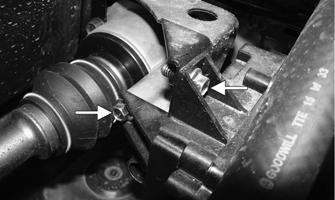
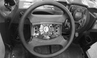
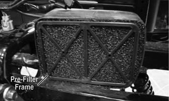
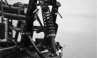
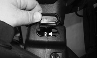
1.Clean the seat cushions with a damp cloth and allow to dry. 2.Clean the vehicle thoroughly by washing dirt, oil, grass, and other foreign matter from the entire vehicle. Allow the vehicle to dry thoroughly. DO NOT get water into any part of the engine or air intake. 3.Either drain the gas tank or add a fuel stabilizer to the gas in the gas tank. 4.Clean the interior of the air filter housing. 5.Plug the hole in the exhaust system with a clean cloth. 6.Apply light oil to the upper steering shaft via the access hole. Remove the rubber plug located on the left side of the steering column cover and plungers of the shock absorbers. CAUTION
Prior to storing this vehicle, it must be properly serviced to prevent rusting and component deterioration.
PK094A
7.Tighten all nuts, bolts, cap screws, and screws. Make sure rivets holding components together are tight.
Replace all loose rivets. Care must be taken that all calibrated nuts, cap screws, and bolts are tightened to specifications. 8.Fill the cooling system to the bottom of the stand pipe in the radiator neck with properly mixed coolant. Check the coolant level in the reservoir tank; it should be in between the MIN and MAX markings. 9.Disconnect the battery cables (negative cable first); then remove the battery, clean the battery posts and cables, and store in a clean, dry area. NOTE: For storage, use a battery maintainer or make
sure the battery is fully charged (see Battery section in this manual).
10.Store the vehicle indoors in a level position.
CAUTION
Avoid storing outside in direct sunlight and avoid using a plastic cover as moisture will collect on the vehicle causing rusting.
Preparation after Storage
Taking this vehicle out of storage and correctly preparing it will ensure many miles and hours of trouble-free riding. The manufacturer recommends the following procedure: 1.Clean the vehicle thoroughly. 2.Clean the engine. Remove the cloth from the exhaust system. 3.Check all control wires and cables for signs of wear or fraying. Replace if necessary. 4.Change the engine/transmission oil and filter. 5.Check the coolant level and add properly mixed coolant as necessary. 6.Charge the battery; then install. Connect the battery cables making sure to connect the positive cable first.
7.Check the entire brake systems (fluid level, pads, etc.), all controls, headlights, taillight, brake light, and headlight aim; adjust or replace if necessary. 8.Check the tire pressure. Inflate to recommended pressure as necessary. 9.Tighten all nuts, bolts, cap screws, and screws making sure all calibrated nuts, cap screws, and bolts are tightened to specifications. 10.Make sure the steering moves freely and does not bind. 11.Check the spark plug. Clean or replace as necessary. 12.Check the air filter and the air filter housing. Clean or replace as necessary.
CAUTION