Electrical System The electrical connections should be checked periodically for proper function. TESTING ELECTRICAL COMPONENTS
All electrical tests should be made using the CATT II or the Fluke Model 88 Multimeter. The CATT II can return data for certain components which are identified at the beginning of their respective sub-section. If any other type of meter is used, readings may vary due to internal circuitry. When troubleshooting a specific component, always verify first that the fuse(s) are good, that the instrument gauge is properly functioning, that the connections are clean and tight, that the battery is fully charged, (with a minimum cranking voltage of approximately 10.8 VDC at the battery), and that all appropriate switches are activated. NOTE: For absolute accuracy, all tests should be made at room temperature of 68° F. NOTE: Certain components and sensors can be checked by using the EFI diagnostic system (see EFI Diagnostic System in this section for more information). SPECIAL TOOLS
A number of special tools must be available to the technician when performing service procedures in this section. Refer to the current Special Tools Catalog for the appropriate tool description. NOTE: When indicated for use, each special tool
will be identified by its specific name, as shown in the chart below, and capitalized. Description Fluke Model 88 Multimeter CATT II
p/n Common Tool 0544-029
MaxiClips
Common Tool
Timing Light
Common Tool
Ignition Test Plug
Common Tool
NOTE: Special tools are available from the Service Department.
After being in service, batteries require regular cleaning and recharging in order to deliver peak performance and maximum service life. The following procedures are recommended for cleaning and maintaining lead-acid batteries. Always read and follow instructions provided with battery chargers and battery products. NOTE: Refer to all warnings and cautions provided with the battery or battery maintainer/charger.
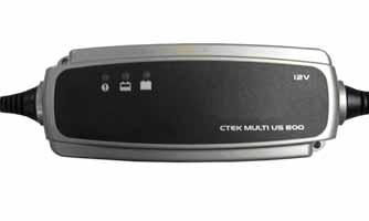
Loss of battery charge may be caused by ambient temperature, ignition OFF current draw, corroded terminals, self discharge, frequent start/stops, and short engine run times. Frequent winch usage, snowplowing, extended low RPM operation, short trips, and high amperage accessory usage are also reasons for battery discharge. Maintenance Charging NOTE: The manufacturer recommends the use of the CTEK Multi US 800 or the CTEK Multi US 3300 for battery maintenance charging. Maintenance charging is required on all batteries not used for more than two weeks or as required by battery drain.
1. When charging a battery in the vehicle, be sure the ignition switch is in the OFF position. NOTE: Be sure to maintain the fluid of the battery at the UPPER LEVEL. Use only distilled water when adding fluid to these batteries.
2. Clean the battery terminals with a solution of baking soda and water. 3. Be sure the charger and battery are in a well-ventilated area and ensure the battery charger cables will not contact any battery acid. Be sure the charger is unplugged from the 110-volt electrical outlet. 4. Connect the red terminal lead from the charger to the positive terminal of the battery; then connect the black terminal lead of the charger to the negative terminal of the battery. 5. Plug the battery charger into a 110-volt electrical outlet. 6. If using the CTEK Multi US 800, there are no further buttons to push. If using the CTEK Multi US 3300, press the Mode button (A) at the left of the charger until the Maintenance Charge Icon (B) at the bottom illuminates. The Normal Charge Indicator (C) should illuminate on the upper portion of the battery charger.
Battery
Component data can be retrieved using the CATT II. Utilize the Sensor Data screen.
NOTE: Preliminary checks may be performed on this component using the diagnostic mode on the LCD gauge (see EFI Diagnostic System in this section).
The battery is located under the seat on the driver’s side.
800A
99